Table of Contents
Advertisement
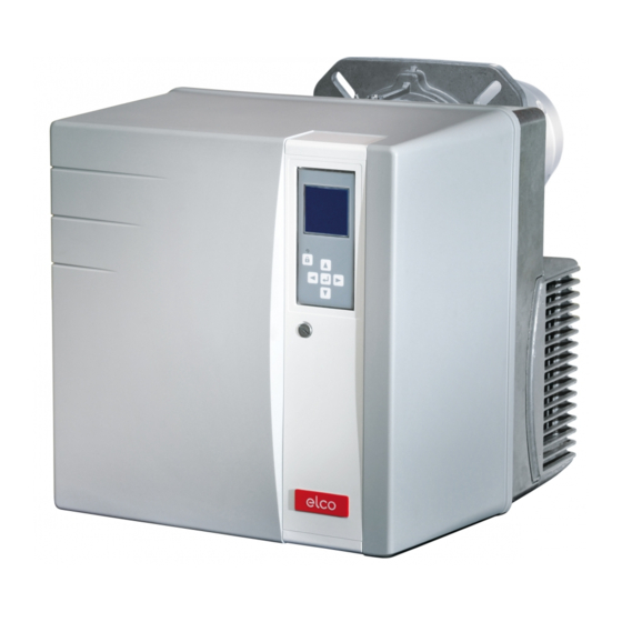
VL 4.460 D
VL 4.610 D
Operating instructions
For specialist installation engineers
Fuel oil burners...................................... 2-25
de, fr..................................... 4200 1032 5500
it, nl ...................................... 4200 1032 5600
............................................. 4200 1032 5300
02/2011 - Art. Nr. 4200 1032 5700A
en
Advertisement
Table of Contents

Related Manuals for elco VL 4.460 D


Summary of Contents for elco VL 4.460 D
- Page 1 VL 4.460 D VL 4.610 D Operating instructions For specialist installation engineers Fuel oil burners........2-25 de, fr........4200 1032 5500 it, nl ........4200 1032 5600 ..........4200 1032 5300 02/2011 - Art. Nr. 4200 1032 5700A...
-
Page 2: Table Of Contents
Machinery directive Important information The following standards should be 2004/108/EC EMC directive The VL 4.460 D and VL 4.610 D burners observed in order to ensure safe, 2006/ 95/EC Low voltage directive are designed to burn extra light fuel oil in... -
Page 3: Burner Description
Overview Burner description Air flap servomotor Automatic combustion control unit Display Flame monitor Auxiliary motor supply relay Blower and pump motor Igniter Adjusting screw for dimension Y Nozzle line hose Housing Plate hanging device Outlet for the hoses Burner tube 7-pin connector 10.1 4-pin connector 10.2 3-pin connector (auxiliary motor supply... -
Page 4: Operating Mode, Safety Function
Operation Operation Safety function Starting the burner - The air flap continues to move to the Safety function - After heat is requested by the boiler full load position. The full load is in A safety shutdown is triggered: regulator, the automatic combustion operation. - Page 5 Operation TCH 2xx safety unit The TCH 2xx fuel oil automatic Locking and unlocking combustion control unit controls and The control unit can be locked using the monitors the forced draught burner. The release knob or unlocked as long as microprocessor-controlled program the unit is powered on.
- Page 6 These are pre-set in the factory. No modifications may be carried out on-site without prior consultation with ELCO. • operating statistics The access code and menu the setting setpoints for these menus are available on request.
- Page 7 Operation TCH 2xx safety unit Operating cycle phases: Starting the burner: opening the the air flap to 0° solenoid valve, flame formation, Awaiting a new heating request No voltage safety time Powering up, no heat request Awaiting regulator release Heating request Opening the air flap, until the Air flap opens to the preventilation opening position of the 2...
-
Page 8: Terminal Allocation Chart, Connection
Operation Terminal allocation chart 230 Volt connection 2nd stage 3rd stage 2nd stage Heating 1st stage Burner motor Ignition solenoid valve solenoid valve thermostat request solenoid valve Connector Terminal L1 power Fault Flame monitor Remote Fuel pump Pre-heater supply Earth Earth pressure display... - Page 9 Operation Terminal allocation chart Low voltage connections Display-PC interface Terminal Connector Connector Terminal Air flap servomotor Terminal Description Connector Terminal Description Connector Not used Not used Not used Not used Not used Not used Not used Not used Not used Not used Not used Not used...
-
Page 10: Fuel Oil Burner Pump
Operation Pump The pump is a gear pump. It must be connected as a two-line pump via a Vacuum connection G 1/4 bleed filter. For the connection of the fuel Return connection G 1/4 oil tank and the bleed filter, it is better to Pump tube connection / use the single line option. -
Page 11: Installing The Burner, Burner Installation Location
Assembly Burner assembly Preparing the boiler front Burner head assembly • Prepare the burner mounting plate/ • Screw the bolts into the burner fixing boiler door in accordance with the plate/boiler door and position the diagram. insulation material. For a drill hole of •... -
Page 12: Electrical Connection Fuel Oil Connection
This directive forms an integral part of the elements ELCO planning is based Fuel oil connection Important: To ensure the operating safety of the • Maximum pressure at the pump intake system, the fuel oil supply must be <... -
Page 13: Checks Before Commissioning
Stage Ignition 1. stage 2. stage 1. stage 2. stage 1. stage 2. stage 1. stage 2. stage 1. stage 2. stage changeover 15,2 23,0 4,00 2,50 VL 4.460 D 17,0 26,0 4,00 2,50 20,0 35,4 5,00 3,50 12,5 16,0... -
Page 14: Air Regulation Fuel Oil Pressure Regulation
Commissioning Air regulation Fuel oil pressure regulation Air regulation The regulation of air in the burner head Combustion air is regulated at two affects not only the air flow but also the points: mixing zone and the air pressure in the •... -
Page 15: Adjusting Burner Output
The screen displays the factory pre- settings for the different positions of the air flap (here for example: for a VL 4.460 D). The following positions for the air flap are presented: - ignition position (when the... - Page 16 Commissioning Pre-setting without flame General advice before starting the burner End of settings menu without flame When all the positions of the servomotor have been determined according to the required settings, it is then possible to move on to the next section for commissioning - "Setting the flame". To do this, place the cursor in the lower part of the screen on the symbol and confirm by pressing the button...
- Page 17 Commissioning Setting the flame - If the boiler heating The air flap switches to the request is not present, the ignition position. boiler remains on standby. In this case, it is still possible to return to the previous setting menu "Pre-setting without flame".
- Page 18 Commissioning Setting the flame Setting the 1st stage If the flame has been detected and stabilised, the control unit sets the burner to the 1st stage as soon as it receives the regulation authorisation. - Adjust the fuel oil pressure for the 1st stage depending on the required output, using the regulator 6 on the pump.
- Page 19 Commissioning Setting the flame Operating mode Closing the "Setting the flame" menu The burner setting is now complete. If necessary, it is possible to again correct each of the settings values. To do this, position the cursor on the value to be modified, using the button Otherwise, at all times, the following possible ways of closing the "Setting the flame"...
- Page 20 Commissioning Saving the adjustment values in the display Saving the adjustment values in the display If the burner setting procedure has been successfully completed, the servomotor positions for all the operating states will be fixed in the control unit. A back-up copy of the values is therefore stored in the display.
-
Page 21: Maintenance
Maintenance Servicing Les travaux d’entretien sur la chaudière Work recommended as part of annual - Check burner start characteristics et sur le brûleur ne doivent être exécutés burner maintenance: - Checking oil pressure and vacuum at exclusivement que par un chauffagiste - Burner test run, input measurement in the burner pump with the burner in spécialiste dûment formé... - Page 22 Maintenance Servicing Replacing the flame tube For this operation, it is necessary to Precautions either open the furnace gate or remove After any operation: check the the burner. combustion performance under real - Variant 1 - Access via the furnace gate operating conditions (doors shut, •...
-
Page 23: Troubleshooting
Maintenance Troubleshooting Malfunction diagnosis and repair Important safety components must not In the event of a malfunction, first check be repaired; these components must be that the prerequisites for correct replaced by parts with the same part operation are fulfilled: number. -
Page 24: Fault Diagnosis Menu
Maintenance Fault diagnosis menu Operating statistics menu Fault diagnosis menu To access the fault diagnosis menu, press any button when the burner is ready to operate, when the burner is in operation, or when it is in malfunction mode. It is not possible to access the fault diagnosis menu during the start-up phase. -
Page 25: Operating Statistics Menu
Maintenance Operating statistics menu - Total number of burner start-ups since the last meter reset - Total number of faults since the last meter reset - Total operating time since the last meter reset - Total operating time in 2nd stage since the last meter reset - Number of "unwanted flame"... - Page 26 02/2011 - Art. Nr. 4200 1032 5700A...
- Page 27 02/2011 - Art. Nr. 4200 1032 5700A...
- Page 28 Hotline ELCO Austria GmbH Aredstr.16-18 0810-400010 2544 Leobersdorf ELCO Belgium nv/sa Z.1 Researchpark 60 02-4631902 1731 Zellik ELCOTHERM AG Sarganserstrasse 100 0848 808 808 7324 Vilters ELCO GmbH Dreieichstr.10 0180-3526180 64546 Mörfelden-Walldorf ELCO Italia S.p.A. Via Roma 64 800-087887 31023 Resana (TV) ELCO Burners B.V.
Need help?
Do you have a question about the VL 4.460 D and is the answer not in the manual?
Questions and answers