Table of Contents
Advertisement
Quick Links
VB 2.. VD
Operating instructions
For specialist installation engineers
Fuel oil burners
de, fr................................. 4200 1046 8002
it, nl.................................. 4200 1046 8102
en..................................... 4200 1046 8202
de, fr, it, nl, en................. 4200 1046 7903
......................................... 420 110 084 400
......................................... 4200 1068 3900
02/2016 - Art. Nr. 4200 1046 8202A
en
Advertisement
Table of Contents

Related Manuals for elco VB 2.** VD Series


Summary of Contents for elco VB 2.** VD Series
- Page 1 VB 2.. VD Operating instructions For specialist installation engineers Fuel oil burners de, fr......... 4200 1046 8002 it, nl........4200 1046 8102 en........4200 1046 8202 de, fr, it, nl, en....4200 1046 7903 ......... 420 110 084 400 ......... 4200 1068 3900 02/2016 - Art.
-
Page 2: Table Of Contents
ÖNORM C1109: standard and low range. Any other type of application the part of the buyer or any third party, sulphur requires the approval of ELCO. including the fitting of non-original BE: NBN T52.716: standard and NBN parts. EN 590: low sulphur... -
Page 3: Burner Description
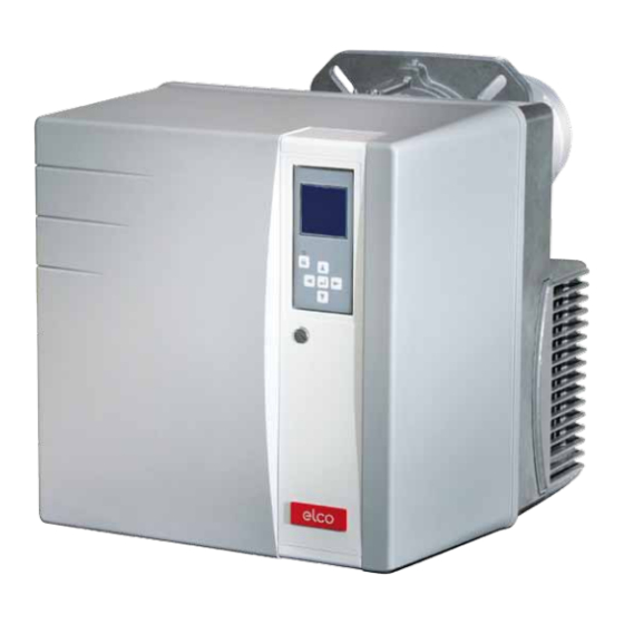
Overview Burner description Control and safety unit Display Flame detector Fan motor Pump motor Igniter Adjusting screw dimension Y (recirculation) Nozzle line tube Base plate Burner pipe Flame tube (supplied disassembled) 7-pin connector (hidden) 10.1 4 pin connector Cover Release knob Hood securing screw Fuel oil pump Fuel oil hoses... -
Page 4: Operating Mode, Safety Function
Operation Operation Safety function Heating function Starting the burner maximum load speed, and maximum load mode is active. If the system demands heat, the pre- - If heat is requested by the boiler regulator, the automatic oil heater is switched on first. combustion control unit starts the Safety function When the oil preheating temperature is... -
Page 5: Automatic Combustion Control Unit
Operation TCH 24x control unit The TCH 24x fuel oil automatic Locking and unlocking combustion control and safety unit The control unit can be locked using the controls and monitors the forced draught release knob or unlocked as long as burner. - Page 6 No modifications may be • Setting/modification carried out on-site menu for standard without prior configurations* consultation with ELCO. The access code and the setting setpoints for these menus are available on request. 02/2016 - Art. Nr. 4200 1046 8202A...
- Page 7 Operation TCH 24x control unit Program sequence phases: increased to the 1st stage No voltage Awaiting authorisation for regulation Powering up, no heating request The fan speed is increased to the Heating request, Verification of fan zero speed, pre-heater on 2nd stage valve opening value Checking the rest status of the air Operation in 2nd stage...
-
Page 8: Terminal Allocation Chart, Connection Socket
Operation Terminal allocation chart 230 Volt connection Heating 2nd stage 2nd stage 3rd stage Blower motor 1st stage Ignition request thermostat solenoid valve solenoid valve solenoid valve Connector Terminal Remote L1 power Fuel oil Fault Flame Pre-heater unlocking Earth Earth supply pump motor pressure... - Page 9 Operation Terminal allocation chart Low voltage connections Fan motor speed regulation control Terminal Connector Connector Terminal Display/PC interface Terminal Description Connector Terminal Description Connector Not used Not used Not used Not used Not used Not used Not used Not used Fan motor speed regulation control Not used Not used...
-
Page 10: Fuel Oil Burner Pump
Operation Pump This is a gear pump. It must be Return connection G1/4 connected as a two-line pump via a Vacuum connection G1/4 Nozzle supply line connection G1/8 bleed filter. For the connection of the fuel Pressure gauge connector oil tank and the bleed filter, it is better to Vacuum gauge connector use the single line option. -
Page 11: Burner Assembly, Burner Installation Position
Installation Burner installation Burner installation location Burner installation Installation: The burner flange 3 features three • Secure connecting flange 3 to the boiler elongated slots and can be used for a using screws 4. drilling Ø of 150 to 170 mm (VB2.38/54 •... -
Page 12: Electrical Connection/Oil Connection
For the maximum values of the suction lengths and heights, see the directive for carrying out and sizing installations with suction. This directive forms an integral part of the elements on which ELCO planning is based. Fuel oil connection Important: To ensure the operating safety of the •... -
Page 13: Checks Before Commissioning Setting Data
Commissioning Checks before commissioning Setting data Checks before commissioning practices. • The heating request must be available. The following must be checked before • The heat generator and heating • Fuel storage tanks must be full. initial commissioning: installation must be filled with water •... -
Page 14: Checking The Combustion Components Recirculation
Commissioning Checking the combustion components Recirculation Ignition electrode gap nozzle/air nozzle distance (dimension Y) VB2.38/54 VD: 3mm VB2.38/54 VD: 2.5mm VB2.66/95 VD: 4-5mm (without VB2.66/95 VD: 4.5mm template) 1. .. Setting the ignition electrodes Position of the ignition electrodes The setting template supplied with the 4: VB2.38/45/54 VD burner may be used for the following functions. -
Page 15: Fuel Oil Pressure Regulation Air Regulation
Commissioning Fuel oil pressure regulation Air regulation Return connection G1/4 Setting the fuel oil pressure The fuel oil pressure is adjusted using Vacuum connection G1/4 fuel oil pressure regulator 8 for the 1st Nozzle supply line connection G1/8 stage and fuel oil pressure regulator 9 Pressure gauge connector for the 2nd stage. -
Page 16: Adjusting Burner Output
Commissioning Pre-setting without flame Setting is carried out in two phases: Important - Pre-setting without flame At this point, no setting position has - Setting the flame, to fine tune the been defined, therefore the burner settings based on the combustion cannot be started under these results conditions. - Page 17 Commissioning Pre-setting without flame General advice before starting the burner End of the setting without flame menu When all the ventilation speed setting positions have been determined according to the required presetting, it is then possible to move on to the next section for commissioning - "Setting the flame".
- Page 18 Commissioning Setting with flame - If the boiler heating The fan speed is decreased to request is not present, the the ignition speed. burner remains on standby. It is still possible to return to the precious setting menu "Pre-setting without flame". To do this, position the cursor on symbol and confirm with the...
- Page 19 Start-up Setting with flame 1st stage adjustment If the flame has been detected and stabilised, the control and safety unit switches the burner to the 1st stage. - Depending on the required output, set the fuel oil pressure to 1st stage using regulator 8 on the pump.
- Page 20 Commissioning Setting with flame Operating mode End of the "Setting with flame" menu The burner setting is now complete. If necessary, it is possible to again correct each of the settings values. To do this, position the cursor on the value to be modified, using the key.
- Page 21 • Fan speed during the pre-ventilation phase. • Activate the option “Configuration for domestic use” from the menu overview. Enter the access code (only available to an ELCO-qualified technician). Access is possible only when the burner is off. Fuel oil heater If no time indication is displayed next to the heater symbol, the heater is off.
- Page 22 Commissioning Menu 5: Configuration for domestic use Adjustment release waiting time • Activate the setting mode using the key. The time starts to flash. • Use keys to decrease or increase the adjustment release waiting time by 1s steps. Adjustment range 0s-255s. •...
- Page 23 Commissioning Menu 5: Configuration for domestic use Complete the settings with a test phase • Confirm the setting with symbol . The burner enters into standby mode and starts a test phase as soon as there is a heating request, or: •...
- Page 24 Start-up Displaying the setting data from the manual control display Displaying the setting data from the manual control display Once the burner setting procedure has been successfully completed in menu 1, the settings for all the operating states are stored in the control unit. At the same time, a back-up copy of the setting values is saved in the display at the end of menu 1.
-
Page 25: Maintenance
Servicing Maintenance Burner and boiler servicing must only Work recommended as part of annual - Check the oil pressure and vacuum at burner maintenance: the burner pump with the burner in be carried out by an approved, - Burner test run, input measurement in operation qualified heating engineer. -
Page 26: Servicing Maintenance
Servicing Maintenance Cleaning the pump filter Cleaning the cover The filter is located in the pump housing. • Do not use abrasive products or It must be cleaned each time the products containing chlorine. equipment is serviced. To do so: •... -
Page 27: Troubleshooting
Servicing Fault repair Cause of faults and troubleshooting Components which fulfil an important In the event of a fault, first check that the safety function must not be repaired. prerequisites for correct operation are These components must be replaced by fulfilled: parts with the same reference number. -
Page 28: Fault Diagnosis Menu Operating Statistics Menu
Servicing Fault diagnosis menu Operating statistics menu Fault diagnosis menu To access the fault diagnosis menu, press any key when the burner is ready to operate, already operating, or in malfunction mode. It is not possible to access the fault diagnosis menu during the start-up phase. -
Page 29: Operating Statistics Menu
Servicing Operating statistics menu - Total number of burner start-ups since the last meter reset - Number of faults since the last meter reset - Total operating time since the last meter reset - Operating time in 2nd stage since the last meter reset - Number of "Unauthorised flame"... - Page 30 02/2016 - Art. Nr. 4200 1046 8202A...
- Page 31 02/2016 - Art. Nr. 4200 1046 8202A...
- Page 32 Made in EU. Non contractual document. 02/2016 - Art. Nr. 4200 1046 8202A...
Need help?
Do you have a question about the VB 2.** VD Series and is the answer not in the manual?
Questions and answers