
Subscribe to Our Youtube Channel
Related Manuals for Satel CSP-204


Summary of Contents for Satel CSP-204
- Page 1 Fire Alarm Control Panel CSP-204 CSP-208 CSP-104 CSP-108 Operation manual Firmware version 1.1 csp-x_o_en 06/15 SATEL sp. z o.o. ul. Budowlanych 66 80-298 Gdańsk POLAND tel. +48 58 320 94 00 www.satel.eu...
-
Page 2: Table Of Contents
4.2.3 Checking availability of the access level 2 operation on the other panel ..... 12 4.2.4 Using the user menu [CSP-204 / CSP-208 / PSP-204 / PSP-208] ......12 Access level 2 operation..................13 4.3.1 Enabling / disabling the two-stage alarm mode............13 4.3.2... -
Page 3: Introduction
CSP-104 - 4 zone conventional fire alarm control panel, CSP-108 - 8 zone conventional fire alarm control panel, CSP-204 - 4 zone conventional fire alarm control panel with LCD display, CSP-208 - 8 zone conventional fire alarm control panel with LCD display. -
Page 4: Front Panel Description
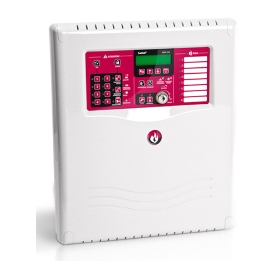
LED indicators; control buttons; insert with zone descriptions to facilitate identification of the alarm source; LCD display to make easier transmission of information (only CSP-204, PSP-204, CSP-208 and PSP-208); key switch to enable changing the access level. - Page 5 CSP-204 ● CSP-208 ● CSP-104 ● CSP-108 SATEL Fig. 4. Front panel of the CSP-204 control panel. Fig. 5. Front panel of the PSP-204 repeater panel.
- Page 6 SATEL Operation manual Fig. 6. Front panel of the CSP-108 control panel. Fig. 7. Front panel of the PSP-108 repeater panel.
-
Page 7: Led Indicators
CSP-204 ● CSP-208 ● CSP-104 ● CSP-108 SATEL Fig. 8. Front panel of the CSP-104 control panel. Fig. 9. Front panel of the PSP-104 repeater panel. 2.1 LED indicators Description Color Indications ON – fault yellow fault blinking – fault memory blinking –... - Page 8 SATEL Operation manual zone 1 zone 2 zone 3 zone 4 blinking – zone fault (short-circuit or break) yellow ON – zone is disabled or is being tested zone 5 zone 6 zone 7 zone 8 blinking – output fault (short-circuit or break)
-
Page 9: Buttons
CSP-204 ● CSP-208 ● CSP-104 ● CSP-108 SATEL ON – control panel is supplied from 230 V AC mains power green blinking – control panel is supplied from a battery (no 230 V AC supply) ON – two-stage alarm mode is enabled (second... - Page 10 SATEL Operation manual - after pressing the button – disables / enables the zone - after pressing the button – starts / stops the zone test - after pressing the button – the buttons 1-4 allow to enter the level 3 access code (programming) - after pressing the button –...
-
Page 11: Conditions Signaled By The Control Panel / Repeater Panel
During normal operation, the green LED, described as POWER, is steadily lit on the front panel. On the display (CSP-204 and CSP-208 control panels, PSP-204 and PSP-208 repeater panels), the time and date (the upper line) and the programmed message (the lower line) are presented. -
Page 12: Operation
SATEL Operation manual lower line: name of the zone which triggered alarm as the last one / consecutive number of the alarm / total number of the alarms. Fault – signaled by: ON yellow LED, described as FAULT; blinking yellow LED, according to the relevant trouble (see section LED INDICATORS p. -
Page 13: Access Level 1 Operation
ON, if the level 2 operation is available on the repeater panel; a message on the LCD display [only CSP-204 and CSP-208] informs you whether the level 2 operation is available on the repeater panel. On the repeater panel Press and hold the button. -
Page 14: Access Level 2 Operation
SATEL Operation manual Use the buttons to scroll the list of alarms up and down. Use the button to exit the function. Viewing the event log After starting the function, information about the last event will be presented on the display: ... -
Page 15: Procedure In The Case Of Alarm Signaling
CSP-204 ● CSP-208 ● CSP-104 ● CSP-108 SATEL 4.3.2 Procedure in the case of alarm signaling 1. Press the button to acknowledge the alarm and silence the acoustic signaling of the control panel / repeater panel. The red LED, described as FIRE, will stop blinking and will come ON. -
Page 16: Testing The Zones
4. Press the button to exit the testing function. 4.3.8 Using the user menu [CSP-204 / CSP-208 / PSP-204 / PSP-208] The way of using the menu and viewing the logs of alarms, events and current faults is described in the access level 1 operation section (p. 12). Additionally, a submenu with... -
Page 17: Using The Virtual Panel
1. Start the web browser. 2. Enter the module IP address into the address bar and press ENTER key. 3. The login page will open in the web browser. Enter the code (by default: satel) to get access to the virtual panel. - Page 18 SATEL Operation manual Fig. 11. Virtual panel. control panel type. icons providing information about the control panel status: - access level 1; - access level 2; - two-stage alarm mode disabled; - two-stage alarm mode enabled; - fire alarm routing output is active;...
- Page 19 CSP-204 ● CSP-208 ● CSP-104 ● CSP-108 SATEL the date and time as per the control panel clock. the area where information on pre-alarms and alarms is displayed. The zone name is preceded by a suitable icon: - pre-alarm; - alarm.
Need help?
Do you have a question about the CSP-204 and is the answer not in the manual?
Questions and answers