Advertisement
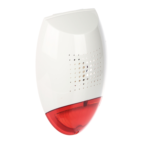
The SP-500 visual-audible siren is designed for application in the burglary and assault
signaling systems. A set of LEDs situated at the lower part of the siren enclosure serves as
the source of light. A modulated acoustic signal is generated by means of the piezoelectric
transducer. Any attempt to open the siren or tear it off from the mounting surface will set off
a tamper alarm. The electronics board is protected by impregnation against unfavorable
effects of weather conditions. As the SP-500 housing is made of the highly impact resistant
PC LEXAN polycarbonate, hence it features a high mechanical strength and guarantees
aesthetic appearance of the siren even after many years of operation.
Explanations for Figure 1:
1
– fixing screw holes
2
– piezoelectric transducer
3
– cable inlet
4
– electronics board
5
– cover fixing screw
6
– cover openings
7
– piezoelectric transducer leads
8
– tamper element – protects the siren from removing its enclosure and/or tearing it off
from the wall (must be screwed to the mounting surface; do not overtighten, so as not
to break the narrowings)
9
– opening for tamper element fixing screw
10 – water drain opening (do not stop)
VISUAL-AUDIBLE SIREN
®
Fig. 1. View of the SP-500 siren enclosure.
SP-500
2
3
4
5
sp500_en 04/09
6
7
8
9
10
Advertisement
Table of Contents

Subscribe to Our Youtube Channel
Related Manuals for Satel SP-500


Summary of Contents for Satel SP-500
- Page 1 Any attempt to open the siren or tear it off from the mounting surface will set off a tamper alarm. The electronics board is protected by impregnation against unfavorable effects of weather conditions. As the SP-500 housing is made of the highly impact resistant PC LEXAN polycarbonate, hence it features a high mechanical strength and guarantees aesthetic appearance of the siren even after many years of operation.
- Page 2 (see Fig. 2). 2. Installation The SP-500 siren is to be installed on a flat surface, in a possibly inaccessible place, so as to minimize the risk of tampering. The siren should be screwed to its base by means of screws and expansion bolts (the screws and expansion bolts are delivered with the siren).
- Page 3 OUT8 SP-500 Fig. 4. Method of connecting the SP-500 siren to low-current outputs of INTEGRA 32 control panel. Output OUT2 has been programmed as supply one. Output OUT3 controls the relay P1 which triggers acoustic signaling, and output OUT4 controls the relay P2 which triggers optical signaling (low-current outputs with normal polarization are activated by shorting the terminal directly to ground 0 V).
-
Page 4: Technical Data
TMP TMP SP-500 Fig. 5. Method of connecting the SP-500 siren to high-current outputs of INTEGRA 32 control panel. Output OUT1 triggers optical signaling and output OUT2 – acoustic signaling (the high-current outputs with normal polarization – activation means that +12 V voltage is supplied).
Need help?
Do you have a question about the SP-500 and is the answer not in the manual?
Questions and answers