Advertisement
The CA-64 E expander is dedicated to interfacing with INTEGRA series or CA-64
alarm control panels. It allows extension of the alarm system by eight zones having
identical features as the zones of the control panel main board. Additionally, the
expander supports vibration and roller shutter motion detectors. This manual applies
to the expander with electronics version 2.1 and firmware version 2.0 (or newer).
1. Description of electronics board
1
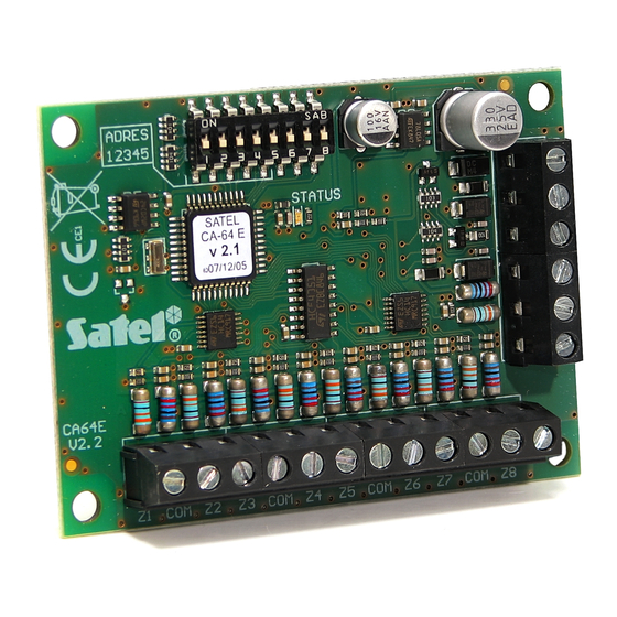
Fig. 1. Schematic view of the expander electronics board.
Legend:
1 – LED SATUS to indicate the process of communication between control panel
and expander:
− blinking – data exchange with the panel;
− ON – no data exchange with the panel (the module and the control panel
connecting wire is damaged, identification of module is not carried out or the
STARTER program is started in the control panel);
2 – package of DIP switches designed for setting individual address of the module
and for selecting the type of supported detectors (see:
Description of the terminals:
Z1...Z8
- zones
COM
– common ground
TMP
– module tamper detection circuit (NC) – if not used, it should be shorted
to ground.
CLK, DTA – expander bus
®
ADRES
12345
Z1 COM Z2
Z3
COM
ZONE EXPANDER
CA-64 E
STATUS
Z5
COM
Z6
COM
Z4
Z7
ca64e_en 08/08
2
Z8
).
DIP
SWITCHES
Advertisement
Table of Contents

Related Manuals for Satel CA-64 E


Summary of Contents for Satel CA-64 E
- Page 1 ® ca64e_en 08/08 The CA-64 E expander is dedicated to interfacing with INTEGRA series or CA-64 alarm control panels. It allows extension of the alarm system by eight zones having identical features as the zones of the control panel main board. Additionally, the expander supports vibration and roller shutter motion detectors.
- Page 2 CA-64E SATEL +12V – expander power supply input (detectors power supply output) 1.1 DIP switches By using the DIP-switches you can set an individual address of a device and select the type of detectors to be served. To set the address, use the 1 to 5 switches. This address must differ from those of the other modules connected to the control panel expander bus.
- Page 3 SATEL CA-64E address: type of supported zones: NO, NC, EOL, 2EOL/NO, 2EOL/NC, vibration and roller (setting for INTEGRA panels with firmware in version 1.05 or later) Fig. 3. Example of DIP switch settings. 2. Mounting and installation Caution: Prior to starting the module hookup, switch off power supply of the security system.
- Page 4 Average current consumption ................18 mA PCB dimensions ..................... 57x80 mm Weight ........................47 g The latest EC declaration of conformity and product approval certificates are available for downloading on website www.satel.pl SATEL sp. z o.o. ul. Schuberta 79 80-172 Gdańsk POLAND tel.
Need help?
Do you have a question about the CA-64 E and is the answer not in the manual?
Questions and answers