Sign In
Upload
Manuals
Brands
Eaton Manuals
Transducer
IQ 250
Eaton IQ 250 Manuals
Manuals and User Guides for Eaton IQ 250. We have
4
Eaton IQ 250 manuals available for free PDF download: User & Installation Manual, Instructional Leaflet, Quick Start Manual
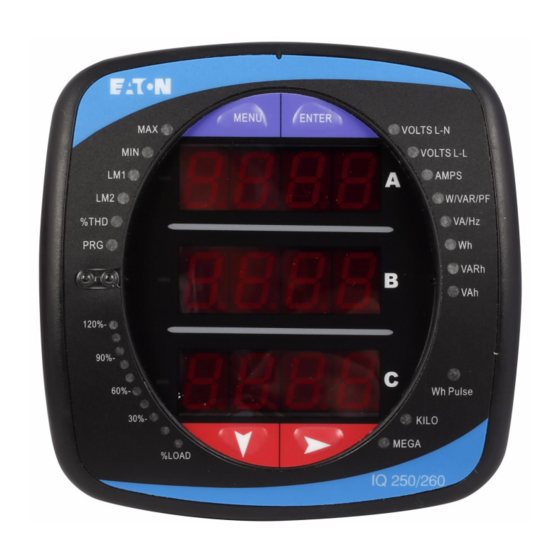
Eaton IQ 250 User & Installation Manual (143 pages)
Low-Cost High Performance Multifunction Electricity Meter
Brand:
Eaton
| Category:
Measuring Instruments
| Size: 6 MB
Table of Contents
Table of Contents
3
Introduction
7
Safety Precautions
8
Overview and Specifications
9
Voltage and Current Inputs
10
CT Pass through
10
Current Gills
10
Ordering Information
11
Measured Values
12
Utility Peak Demand
13
Specifications
13
Accuracy
16
Mechanical Installation
17
Dimensions
17
IQ Transducer Installation
21
DIN Rail Mounting Procedure
21
Electrical Installation
23
Considerations When Installing Meters
23
CT Leads Terminated to Meter
24
CT Leads Pass through
25
Quick Connect Crimp-On Terminations
26
Voltage and Power Supply Connections
27
Ground Connections
27
Voltage Fuses
27
Voltage Connections
27
Electrical Connection Diagrams
28
RS485 / KYZ Output
39
IQ 250/260 Communication
39
Communication Installation
39
2-Wire RS485 Connection
40
RS485 Daisy Chain Connection
40
Using the Power Xpert Gateway
42
IQ 250/260T Communication Information
42
Meter Connection
42
Using the IQ 250/260
43
Understanding Meter Face Elements
43
Understanding Meter Face Buttons
43
Understanding Startup and Default Displays
44
Using the Front Panel
44
Using the Main Menu
45
Using Reset Mode
45
Entering a Password
46
Using Configuration Mode
47
To Access Configuration Mode
47
Configuring the Scroll Feature
48
To Enable or Disable Auto-Scrolling
48
Example CT Settings
49
Configuring CT Setting
49
Configuring PT Setting
50
Configuring Connection Setting
51
Configuring Communication Port Setting
51
Using Operating Mode
52
Operating Mode Parameter Readings
52
Possible Readings
52
Understanding the % of Load Bar
53
Performing Watt-Hour Accuracy Testing
54
Using the I/O Option Cards
55
Installing Option Cards
56
Configuring Option Cards
56
Digital Output / Digital Input Card
57
Wiring Diagram
58
Pulse Output / Digital Input Card
59
1Ma Output Card
61
20Ma Output Card
63
Programming the IQ 250/260
65
Connecting to the IQ 250/260
65
Selecting Settings
66
Accessing the IQ 250/260 Device Profile
66
Performing Tasks
67
Viewing Errors Output Log
69
Viewing Last Update Information
69
Configuration Settings
70
Configuring CT, PT Ratios and System Hookup
70
CT Ratios
70
PT Ratios
70
Configuring Time Settings
71
Configuring System Settings
71
Configuring Communications Settings
72
Setting Display Configuration
73
Configuring Energy, Power Scaling, and Averaging
74
Energy Scaling
74
Demand Averaging
74
Energy Settings
75
Power Settings
75
Configuring Limits
76
Functional Overview for Limits
76
To Configure a Limit
77
Configuring I/O Option Cards
78
Option Card Screens
78
Configuring a Relay Output/Digital Input Card
79
Configuring a Pulse Output/Digital Input Card
81
Configuring a 0-1 Ma Output Card
83
Configuring a 4-20 Ma Output Card
84
Polling the IQ 250/260 Meter
85
Instantaneous Polling
86
Poll Max and Min Readings
87
Poll Power and Energy
88
Poll Accumulators
88
Poll Phasors
89
Poll Status Inputs
90
Poll Limits
91
Using the IQ 250/260 Tools Menu
92
Accessing the Device Profile Screen
92
Setting Device Time
92
Retrieving Device Time
92
Viewing Option Card Information
93
Retrieving Device Status
93
Resetting Device Information
93
Performing Manual Relay Control
94
Performing Firmware Flash Update
94
Using Connection Manager
95
List of Locations
95
To Add a Location
95
To Add a Device
95
To Sort List of Locations
96
To Remove a Location
96
To Edit a Location
96
To Edit a Device
96
Disconnecting from an IQ 250/260
97
To Connect to a Location
97
Changing the Primary Device/Address
97
Merging Connection Databaes
97
Using the Options Screen
98
Using the Help Menu
98
IQ 250/260 Navigation Maps
99
Main Menu Screens
100
Operating Mode Screens
101
Reset Mode Screens
102
Configuration Mode Screens
103
Modbus Mapping for IQ 250/260
105
Modbus Register Map Sections
105
Data Formats
105
Floating Point Values
106
Formula Explanation
106
Modbus Register Map (MM-1 to MM-22)
106
Data Link Layer
135
Using DNP Mapping for IQ 250/260
135
Physical Layer
135
Application Layer
136
Error Reply
136
DNP Lite Register Map
137
Object 10 – Binary Output States
137
Object 12 – Control Relay Outputs
137
Object 20 – Binary Counters (Primary Readings)
137
Analog Inputs (Secondary Readings)
138
Appendix C: Request 05 64 1A C4 Dst Src Crc
139
DNP Message Layouts
139
Link Layer Related Frames
139
Internal Indicator
139
Link Status
140
Application Layer Related Frames
140
Reset Energy
141
Switch to Modbus
141
Reset Demand (Maximums & Minimums)
141
(Alternate) CX Cy 05 0C
141
Advertisement
Eaton IQ 250 User & Installation Manual (142 pages)
Multifunction Electricity Meter
Brand:
Eaton
| Category:
Measuring Instruments
| Size: 13 MB
Table of Contents
Table of Contents
3
Introduction
7
About this Manual
7
Warranty and Liability Information
7
Safety Precautions
7
2 IQ 250/260 Overview and Specifications
9
IQ 250/260 Overview
9
Voltage and Current Inputs
10
Ordering Information
11
Measured Values
12
Utility Peak Demand
13
Specifications
13
Compliance
16
Accuracy
16
Mechanical Installation
17
Introduction
17
ANSI Installation Steps
19
DIN Installation Steps
20
IQ 250/260T Transducer Installation
21
Electrical Installation
23
Considerations When Installing Meters
23
CT Leads Terminated to Meter
24
CT Leads Pass through (no Meter Termination)
25
Quick Connect Crimp-On Terminations
26
Voltage and Power Supply Connections
27
Ground Connections
27
Voltage Fuses
27
Electrical Connection Diagrams
28
Www.eaton.com IB02601006E
29
Communication Installation
39
IQ 250/260 Communication
39
KYZ Output (Com 2)
39
Using the Power Xpert® Gateway
42
IQ 250/260T Communication Information
42
Using the IQ 250/260
43
Introduction
43
Understanding Meter Face Elements
43
Understanding Meter Face Buttons
43
Using the Front Panel
44
Understanding Startup and Default Displays
44
Using the Main Menu
45
Using Reset Mode
45
Entering a Passwords
46
Using Configuration Mode
47
Configuring the Scroll Feature
48
Configuring CT Setting
49
Configuring PT Setting
50
Configuring Connection Setting
51
Configuring Communication Port Setting
51
Using Operating Mode
52
Understanding the % of Load Bar
53
Performing Watt-Hour Accuracy Testing (Verification)
54
Using the IQ 250/260 I/O Option Cards
55
Overview
55
Installing Option Cards
56
Configuring Option Cards
56
Digital Output (Relay Contact)/Digital Input Card
57
Specifications
57
Wiring Diagram
58
Pulse Output (Solid State Relay Contacts)/Digital Input Card
59
Specifications
59
Default Configuration
59
Wiring Diagram
60
1Ma Output Card
61
Specifications
61
Default Configuration
61
Wiring Diagram
62
20Ma Output Card
63
Specifications
63
Default Configuration
63
Wiring Diagram
64
Programming the IQ 250/260
65
Overview
65
Connecting to the IQ 250/260
65
Accessing the IQ 250/260 Device Profile
66
Selecting Settings
66
Performing Tasks
67
Configuring Settings
70
Configuring CT, PT Ratios and System Hookup
70
Configuring Time Settings
71
Configuring System Settings
71
Configuring Communications Settings
72
Setting Display Configuration
73
Configuring Energy, Power Scaling, and Averaging
74
Configuring Limits (IQ 260 Only)
76
Configuring I/O Option Cards
78
Configuring a Relay Output/Digital Input Card
79
Configuring a Pulse Output/Digital Input Card
81
Configuring a 0-1Ma Output Card
83
Configuring a 4-20Ma Output Card
84
Polling the IQ 250/260 Meter
85
Instantaneous Polling
86
Poll Max and Min Readings
87
Poll Power and Energy
88
Poll Accumulators
88
Poll Phasors
89
Poll Status Inputs
90
Poll Limits (IQ 260 Only)
91
Using the IQ 250/260 Tools Menu
92
Accessing the Device Profile Screen
92
Setting Device Time
92
Retrieving Device Time
92
Resetting Device Information
93
Retrieving Device Status
93
Viewing Option Card Information
93
Performing Manual Relay Control
94
Performing Firmware Flash Update
94
Performing Additional Tasks with IQ 250/260 Configuration Software
95
Using Connection Manager
95
Disconnecting from an IQ 250/260
97
Changing the Primary Device/Address
97
Merging Connection Databases
97
Using the Options Screen
98
Using the Help Menu
98
Appendix A - IQ 250/260 Navigation Maps
99
Introduction
99
Navigation Maps
101
Appendix B - Modbus Mapping for IQ
105
Introduction
105
Modbus Register Map Sections
105
Data Formats
105
Floating Point Values
106
Modbus Register Map (MM-1 to
106
Appendix C - Using DNP Mapping for IQ
135
Overview
135
Physical Layer
135
Data Link Layer
135
Application Layer
136
Error Reply
136
DNP Lite Register Map
137
DNP Message Layouts
139
Eaton IQ 250 Instructional Leaflet (13 pages)
Enclosed meter
Brand:
Eaton
| Category:
Measuring Instruments
| Size: 0 MB
Advertisement
Eaton IQ 250 Quick Start Manual (2 pages)
Brand:
Eaton
| Category:
Transducer
| Size: 0 MB
Table of Contents
Mechanical Installation
1
Installation Steps
1
Electrical Wiring Diagrams
1
Program the IQ 250/260T Using RS-485
2
Communication Wiring
2
Factory Initial Default Settings
2
Connection Steps
2
Configuration Steps
2
Scaling (CT, PT Ratios and System Wiring)
2
Communications Settings
2
Update Device
2
Advertisement
Related Products
Eaton IQ 260
eaton IQ 200
Eaton IQ 250S
Eaton IQ250MA65100
Eaton IQ250MA65110
Eaton IQ250MA65114
Eaton IQ260MA65100
Eaton IQ260MA65110
Eaton IQ260MA65114
Eaton Cutler-Hammer IQ DP-4000
Eaton Categories
UPS
Circuit breakers
Switch
Industrial Equipment
Industrial Electrical
More Eaton Manuals
Login
Sign In
OR
Sign in with Facebook
Sign in with Google
Upload manual
Upload from disk
Upload from URL