Table of Contents
Advertisement
Advertisement
Table of Contents

Related Manuals for Eaton MGR10


Summary of Contents for Eaton MGR10
- Page 1 Operating manual MGR10 - English SEFELEC REFERENCE PENT0060...
- Page 2 Changes in the unit not approved by SEFELEC will cancel this warranty. SEFELEC will not be liable for any indirect damages resulting of the use of the unit. This warranty is in lieu of all other warranties. MGR10 A/B/C - Revision : I (for 7.0 software revision)
-
Page 3: Table Of Contents
6-1 PLC remote control ( option MGR10-02) ........................47 6-1-1 Unit setup : ................................47 6-1- 2 Contact specifications : ............................47 6-1-3 Logical states definition : ............................. 48 6-1- 4 Connection : ................................. 48 MGR10 A/B/C - Revision : I (for 7.0 software revision) - Page 4 6-1- 6 How to trigger a measurement : ........................51 6-1-7 Analog output : ..............................51 6.2 RS232 and IEEE488 PROGRAMMING INTERFACES : ................... 53 6.2.1 RS-232 SERIAL INTERFACE ( option MGR10-01 ) ..................53 6.2.1.1 Connection ................................53 6.2.1.2 Front Panel Set-up ..............................54 6.2.2 IEEE-488 PARALLEL INTERFACE (OPTION MGR10-06) .................
-
Page 5: Section 1. Introduction
MEANING OF THE DIFFERENT SYMBOLS ON THE INSTRUMENT Warning (See document attached) Warning, risk of electric chock. DC voltage. AC and DC voltages. AC voltage. Earth connection. MGR10 A/B/C - Revision : I (for 7.0 software revision) -
Page 6: Overview
1.1 OVERVIEW The MGR10 Microhmmeter is a high accuracy instrument designed for industrial and laboratory resistance measurements. Features include: Programmable measuring current user selectable in 100 steps Temperature Compensation Hi/Lo Limits with red/green front panel warning Pass/Fail lamps ... - Page 7 The MGR10 is a true four wire measuring instrument eliminating the need to compensate for lead resistance. The measured value is displayed in large characters with decimal point and units k, , or m. For maximum accuracy the measuring current may be automatically reversed and the average of measurement displayed.
-
Page 8: Definitions And Terminology
Digital filter for smoothing display 1.3 Principles of measurement The MGR10 generates a constant current which is connected using the +I and -I leads across the unknown resistance to be measured. This current also passes through a stable and accurate internal standard. -
Page 9: Mgr10 And Mgr10A Technical Specifications
±(0.05Rdg+0.02%FS) 3 k ±(0.03%Rdg+0.01%FS) ±(0.04Rdg+0.01%FS) ±(0.05Rdg+0.01%FS) 300 ±(0.03%Rdg+0.01%FS) ±(0.04Rdg+0.01%FS) ±(0.05Rdg+0.01%FS) 30 ±(0.03%Rdg+0.01%FS) ±(0.04Rdg+0.01%FS) ±(0.05Rdg+0.01%FS) 3 ±(0.03%Rdg+0.01%FS) ±(0.04Rdg+0.01%FS) ±(0.05Rdg+0.01%FS) 200m ±(0.03%Rdg+0.01%FS) ±(0.04Rdg+0.01%FS) ±(0.05Rdg+0.01%FS) 30m ±(0.03%Rdg+0.01%FS) ±(0.04Rdg+0.01%FS) ±(0.05Rdg+0.01%FS) 3m ±(0.03%Rdg+0.02%FS) ±(0.04Rdg+0.02%FS) ±(0.05Rdg+0.02%FS) MGR10 A/B/C - Revision : I (for 7.0 software revision) -
Page 10: Mgr10B Technical Specifications
±(0.03%Rdg+0.02%FS) ±(0.04%Rdg+0.02%FS) ±(0.05Rdg+0.02%FS) 3 k ±(0.03%Rdg+0.01%FS) ±(0.04Rdg+0.01%FS) ±(0.05Rdg+0.01%FS) 300 ±(0.03%Rdg+0.01%FS) ±(0.04Rdg+0.01%FS) ±(0.05Rdg+0.01%FS) 30 ±(0.03%Rdg+0.01%FS) ±(0.04Rdg+0.01%FS) ±(0.05Rdg+0.01%FS) 3 ±(0.05%Rdg+0.01%FS) ±(0.06Rdg+0.01%FS) ±(0.07Rdg+0.01%FS) 200m ±(0.05%Rdg+0.01%FS) ±(0.06Rdg+0.01%FS) ±(0.07Rdg+0.01%FS) Not available 30m Not available 3m MGR10 A/B/C - Revision : I (for 7.0 software revision) -
Page 11: Mgr10C Technical Specifications
10mA Not available 3 Not available 200m Not available 30m Not available 3m The accuracy of the current is ± 1% . Open circuit voltage is 2 V +/-5% . MGR10 A/B/C - Revision : I (for 7.0 software revision) -
Page 12: Common Specification To All Model Numbers
The temperature measurement range is 0…+40C and the resistance measurement is referenced to 20C when this option is used. Accuracy of the MGR10-04 sensor : +/- ( 0.2% + 1°C) 1.7.2 Lead resistance A maximum lead resistance of 0.5 / Imes ( = 0.05... -
Page 13: Operating Conditions
CAT II. Rate of pollution : Pollution 2 : Occasional conductive pollution only by condensation. Safety class : Class I instrument : Earth protection by mains connection. MGR10 A/B/C - Revision : I (for 7.0 software revision) -
Page 14: Section 2 : Setting Up The Mgr10
Under no circumstance should the equipment be operated with earth disconnected. 2.2 Unpacking the instrument When you unpack the MGR10, check that the following items are present before starting to use the unit: 1 x MGR10 Microhmmeter ... -
Page 15: Section 3 : About The Mgr10
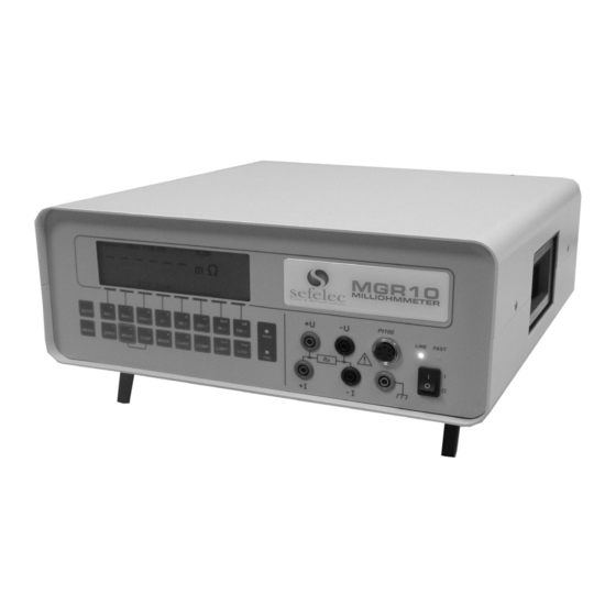
3.1 The Front Panel 3.2 ON/OFF Switch The On/Off switch switches the MGR10 on and off. During Power On the last measurement function setup is restored. The rear mounted cooling fan will always run and the cooling vent must not be blocked. -
Page 16: Summary Of Basic Functions
Direct 30k Selects 30k range from using the 30k range keypad Auto selects autorange The instrument will select the optimum Direct range required and display the measured from value keypad MGR10 A/B/C - Revision : I (for 7.0 software revision) - Page 17 Data logging Selects the data logging and statistical Menu function analysis menu functions Limit functions Selects Hi/Lo limit menu Menu LIMIT MENU Menu functions Selects interface options and calibration Menu functions MGR10 A/B/C - Revision : I (for 7.0 software revision)
-
Page 18: About The Mgr10 Display Screen
= 18.006m (Cu) Meas Cont The keypad below the display screen controls the MGR10. Some keys perform a function directly. For example, selects 3m range. 3m Other keys switch the display to configuration mode which allows you to select options through a series of menus. -
Page 19: About The Function Keys
The top row of function keys are only used to select menu options. The lower row of function keys is enabled only when entering values; these instances are covered later in this section. Both rows of function keys are shown in figure 3.# Figure 3.6.1 - Function keys MGR10 A/B/C - Revision : I (for 7.0 software revision) - Page 20 The rest of this section describes each key in detail and gives examples of how to configure the measurement to your requirements. The last used set up conditions are stored when the instrument is turned off and restored upon switch on. MGR10 A/B/C - Revision : I (for 7.0 software revision)
-
Page 21: Section 4 : Setting Up Measurement Parameters
The range mode selected is indicated in the top left corner of the display. WARNING : The maximum measurement current is 10 A on the 3 lowest ranges , check if the current level intensity selected cannot damaged the resistor under test . MGR10 A/B/C - Revision : I (for 7.0 software revision) -
Page 22: Current Selection
The current value is displayed on the center top line of the LCD screen . The % value is applied to all the ranges . Press on [QUIT ] to escape the menu . MGR10 A/B/C - Revision : I (for 7.0 software revision) -
Page 23: Measurement Mode
Mode Rate Filt Sett Quit For the greatest flexibility and versatility of measurement the MGR10 has many advanced features which can be selected from this menu. km function gives the possibility to display the measured resistances on a known length of cables computed to the value for 1 kilometer. - Page 24 220 ohms / 220 ohmxkm x 2 = 2 kilometer NOTA : the km value will be displayed in big characters and the true value will be displayed in small characters ( Rx= 220,00 ohm) MGR10 A/B/C - Revision : I (for 7.0 software revision)
- Page 25 MGR10 A/B/C - Revision : I (for 7.0 software revision)
- Page 26 LCD screen if the filter is activated . Filt : n Or press on [OK] to keep the previous value Press on [On] to activate the filter mode. MGR10 A/B/C - Revision : I (for 7.0 software revision)
- Page 27 However, if ‘CONTINUOUS’ trigger mode is used, then the operation is the same, except that once the measurement has settled, the settling facility is effectively disabled, and the MGR10 continues to take measurements without interrupting the current, until ‘STOP’ is pressed. When ‘MEAS’ is pressed again, the Settling facility will be re-engaged.
-
Page 28: Temperature Compensation
Press on [Mode] to select the temperature compensation Press on [Ext] to select an external temperature sensor .This mode require the connection of a PT100 sensor on the front panel connector named Pt100. MGR10 A/B/C - Revision : I (for 7.0 software revision) - Page 29 Press on [On] to activate the temperature compensation mode Off : Or press on [Off] to cancel the temperature compensation mode Press on [Quit] to escape the menu MGR10 A/B/C - Revision : I (for 7.0 software revision)
- Page 30 . Figure 4.4.1 Measurement screen with temperature compensation AUTO1: 30m +10.0A (AVE) SLOW + 9.619 m T= + 30.0C (Man) RX = 9.997 m (Cu) Meas Sing MGR10 A/B/C - Revision : I (for 7.0 software revision)
-
Page 31: Limits
Press on [ On] to activate the comparison mode Press on [Off] to cancel the comparison mode. Press on [OK] to go back to the previous page MGR10 A/B/C - Revision : I (for 7.0 software revision) - Page 32 Red Fail LED will light and the warning beeper will sound if the measured value is higher than the Max limit set or lower than the Min limit set. The MGR10 screen will also display PASS or FAILED with >> to show value to high and<< to show value to low.
-
Page 33: Data Logging Function
Press [MENU] key to get the first page : WARNING : if any log have been stored , escape the menu by pressing the [3 k /Quit] key and start storage by performing measurements MGR10 A/B/C - Revision : I (for 7.0 software revision) - Page 34 Escape the menu and trigger at least 2 measurements . The following values will be computed and displayed Minimum value [Min] Maximum value [Max] Mean value [Mean] Peak to Peak value [PtP] Standard Deviation [SD] MGR10 A/B/C - Revision : I (for 7.0 software revision)
- Page 35 Press [No] to keep the measurements and press on [LOG ] key to display the values . Or press [Yes ] to start a new log session in clearing the previous measurements . MGR10 A/B/C - Revision : I (for 7.0 software revision)
-
Page 36: General Setup Menu
Press [List] to get the memory list : Mem 0 In use Mem 5 Free Mem 1 In use Mem 6 Free Mem 2 In use Mem 7 Free Mem 3 In use Mem 8 Free MGR10 A/B/C - Revision : I (for 7.0 software revision) - Page 37 Press [OK] to go back to the previous page Press on [Line Freq ] to select the line frequency to insure a good measurement stability . Press on [50] for a 50Hz line frequency (Europe) MGR10 A/B/C - Revision : I (for 7.0 software revision)
- Page 38 Press on [RS232] to select the serial interface . A message ‘OPTION NOT AVAILABLE’ will be displayed if the unit is not equipped with this option ( MGR10-01) . If the unit is equipped , the ‘RS232’ message will be displayed in the LCD screen upper corner .
- Page 39 , then the ‘INCORRECT’ message will be displayed . Please ask to your operator for the new password or call our service department . The access control to the MGR10 functions is done on 3 levels : [All] : access to all the functions ...
-
Page 40: Measure/Hold Function
WARNING : when measuring with a 10A current , it is possible to create small sparks during connection and disconnection of the specimen . To avoid damaging the specimen under test , please make the connection and disconnection without current flowing . MGR10 A/B/C - Revision : I (for 7.0 software revision) -
Page 41: Measure Stop Function
Press [ZERO ] to null the current display reading to zero, all subsequent measurements will be relative to the null value. Pressing [ZERO] again cancels the zero. Changing range or selecting auto range also cancels the zero. MGR10 A/B/C - Revision : I (for 7.0 software revision) -
Page 42: Section 5 : Measuring With The Mgr10
SECTION 5 : MEASURING WITH THE MGR10 5.1 Connecting to the MGR10 The MGR10 uses a four terminal method of measurement which eliminates errors due to lead resistance. The measuring leads plug into the four front panel safety sockets. The sockets are marked +U, -U, +I, &... -
Page 43: Connecting To The Resistance
5.2 Connecting to the resistance The Digital Microhmmeter MGR10 employs a four wire method of measurement, ie it is necessary to make four connections to the resistance under test. The instrument is supplied with four leads; two for the potential connections which are made across the test resistor at the points between which the resistance is to be determined;... -
Page 44: Resistance Measurement
The compensated resistance value will be displayed in large digits on the MGR10 screen and the measured value will be shown in smaller digits below the main display. The measured or set temperature will also be shown. -
Page 45: Measurement With Limits
HI with chevron pointing to the right for value to high. Figure 4.2.6 Measurement display with limits value to low AUTO1: 30m +10.0A (AVE) SLOW + 9.620 m 10.000 m << LO << 15.000 m Meas Sing MGR10 A/B/C - Revision : I (for 7.0 software revision) - Page 46 Figure 4.2.7 Measurement display with limits value to high AUTO1: 30m +10.0A (AVE) SLOW + 9.620 m 5.0000 m >> HI >> 9.000 m Meas Sing MGR10 A/B/C - Revision : I (for 7.0 software revision)
-
Page 47: Section 6 :Remote Control Interface
6-1-1 Unit setup : The MGR10 unit must be setup in the following conditions : Select the PLC mode by pressing the MENU key , then REM IO , and PLC ( PLC displayed in the LCD screen right corner) Trigger mode : SINGLE ( see chapter 4.3 : Measurement mode ) -
Page 48: Logical States Definition
Output for PLC option : FAIL LOW Output for PLC option : CTRLOUT Output for PLC option : EOT Output for PLC option : ERROR 0-10 volts output , positive pole Not connected MGR10 A/B/C - Revision : I (for 7.0 software revision) - Page 49 In case of connection with a PLC system or any other relay control system, make sure to use shielded wire with braid connected to the metallic cover of Sub-D connector (connection at 360°, shielding connected at each side of the cable). MGR10 A/B/C - Revision : I (for 7.0 software revision)
- Page 50 : the contact of the relay is closed when the test fail by values too low . * ERROR (output) : the contact of the relay is closed when an error occurs (connection error , resistor too high ,….) MGR10 A/B/C - Revision : I (for 7.0 software revision)
-
Page 51: How To Trigger A Measurement
6-1-7 Analog output : The MGR10-02 option provide also an analog output from 0 to 3 volts , corresponding to the measured resistance ( value displayed in big characters ) . A 30 000 digits display matches to a 3.000 volts on the analog output . - Page 52 PLC SYSTEME MGR10 MGR10-02 PLC option connection when using the internal power supply . MGR10 A/B/C - Revision : I (for 7.0 software revision)
-
Page 53: Rs232 And Ieee488 Programming Interfaces
(if the PC sends one it may be lost). As soon as space becomes available in the receiver buffer, RTS is re-asserted to allow the MGR10 A/B/C - Revision : I (for 7.0 software revision) -
Page 54: Front Panel Set-Up
On selecting Baud Rate, the current setting is displayed. This defaults to 9600 following a RESET operation and is the usual setting on shipment. If this is acceptable press “OK”. MGR10 A/B/C - Revision : I (for 7.0 software revision) - Page 55 These set the Baud rate for both transmit and receive. The data word format is fixed at; Start bit; Data word length; 8 bits Parity checking; None Stop bit; Software handshaking using XON/XOFF is not implemented. MGR10 A/B/C - Revision : I (for 7.0 software revision)
-
Page 56: Ieee-488 Parallel Interface (Option Mgr10-06)
Addresses 0 to 30 are recognised as valid addresses for full bus communication. Address 31 is used to isolate an instrument from the bus without the need to disconnect it physically. MGR10 A/B/C - Revision : I (for 7.0 software revision) -
Page 57: Interface Functions
The parallel poll function is not implemented. Device Clear Function The device may be set to the default state by the appropriate command, and includes a selective device clear. Device Trigger Function MGR10 A/B/C - Revision : I (for 7.0 software revision) -
Page 58: Single Wire Interface Messages
Asserted by the listener to indicate that it is busy and is not ready to receive data. NDAC Not Data Accepted Negated by the listener to confirm receipt of a data byte. MGR10 A/B/C - Revision : I (for 7.0 software revision) - Page 59 ATN places the interface in the Data Mode where the active talker sources device dependent Data to all active listeners. Addresses are sent over the bus during the Command Mode. MGR10 A/B/C - Revision : I (for 7.0 software revision)
-
Page 60: Multiwire Interface Messages (Atn True)
- The parser is reset to await a new command. - The output queue is flushed. - The instrument is put into the Operation Complete Command Idle State and the Operation Complete Query Idle State. MGR10 A/B/C - Revision : I (for 7.0 software revision) - Page 61 The ‘Talk’ legend is turned off. Parallel Poll Enable Parallel Poll is not implemented. This command is ignored. Parallel Poll Disable Parallel Poll is not implemented. This command is ignored. MGR10 A/B/C - Revision : I (for 7.0 software revision)
-
Page 62: Device Dependent Messages (Atn False)
It is advisable, though not mandatory, to poll every device to be sure to find every requestor and also to send Serial Poll Disable (SPD) and Untalk (UNT) at the end of the procedure. Parallel Poll Parallel Poll is not implemented. MGR10 A/B/C - Revision : I (for 7.0 software revision) -
Page 63: Programming The Rs-232 & Ieee Interfaces
‘command error’ bit (5) of the Standard Event Register is set. The microhmmeter will not accept whitespace characters in the subsequent parameter list. These will set the ‘command error’ bit (5) of the Standard Event Register. MGR10 A/B/C - Revision : I (for 7.0 software revision) - Page 64 “ string” indicates an ASCII text string. Data Types The bus controller can also send data in a range of formats, but the instrument always responds in a MGR10 A/B/C - Revision : I (for 7.0 software revision)
- Page 65 Measurement queries always return values expressed in Ohms or Degrees, but the units are omitted. Resistance values are returned with engineering exponents reflecting the resolution and units displayed on the LCD screen. e.g. Display Returned Value 30.321 30.321 (30 range) MGR10 A/B/C - Revision : I (for 7.0 software revision)
-
Page 66: Configuration & Measurement Commands
These commands allow the measurement configuration to be set up, but they do not trigger a measurement. SENSe:FRESistance:RANGe <range> Sets the resistance measurement according to the following parameters. The current measurement is aborted. MGR10 A/B/C - Revision : I (for 7.0 software revision) - Page 67 ASCII string containing the appropriate parameter values as above. The current measurement is not affected. The response is an ASCII string of the form: “< range >, < auto mode >” where, range = 3MOHM to 30KOHM (as in tables above) MGR10 A/B/C - Revision : I (for 7.0 software revision)
- Page 68 = AUTO OFF, AUTO1, AUTO2 MGR10 A/B/C - Revision : I (for 7.0 software revision)
- Page 69 Returns the measuring current magnitude and mode currently in force. The response is of the following form: <magnitude>,<“current mode”> containing the appropriate parameter values as above. The current measurement is not affected. MGR10 A/B/C - Revision : I (for 7.0 software revision)
- Page 70 Returns the value of the last measurement made. This is normally used in conjunction with the INITiate command. If CONTinuous triggering is “off”, then INITiate followed by FETCh? will be MGR10 A/B/C - Revision : I (for 7.0 software revision)
- Page 71 ABORt Stops the current measurement and clears the input and output buffers. ABORt works for RS-232 only. If sent in IEEE-488 mode, it will generate a “command error”. MGR10 A/B/C - Revision : I (for 7.0 software revision)
-
Page 72: Data Operation Commands
Forces the microhmmeter to ‘STOP’ mode. The current measurement is aborted. If the log has not reached the COUNt value, STARt or STEP can be used to continue the log from this point. MGR10 A/B/C - Revision : I (for 7.0 software revision) - Page 73 Returns the peak-to-peak value of the resistance values stored in the data log, i.e. max to min. CALCulate: DATA:SDEViation? Returns the standard deviation of the resistance values stored in the data log. This is effectively a measure of rms noise. MGR10 A/B/C - Revision : I (for 7.0 software revision)
- Page 74 Enables or disables the measurement limit facility. CALCulate:LIMit:STATe? Returns “0” (OFF) or “1” (ON). CALCulate:LIMit:ALARm <ON|OFF> or <1|0> Enables or disables the 'failed limit’ audible alarm. CALCulate:LIMit:ALARm? Returns “0” (OFF) or “1” (ON). MGR10 A/B/C - Revision : I (for 7.0 software revision)
-
Page 75: Other Function Commands
(normally 20ºC). It is entered in the current temperature unit (ºC or ºF). Range is 0 - 50ºC (32 - 122°F), in integer values of ºC, or the ºF equivalent. SENSe:TCOMpensate:REFerence? Returns the reference temperature in the current temperature unit. MGR10 A/B/C - Revision : I (for 7.0 software revision) - Page 76 SOURce:VOLTage:LIMit:LEVel? Returns “0” (OFF), “20” (20mV) or “50” (50mV). The MGR10C does not have this facility, and sending this query will generate a “query error”. MGR10 A/B/C - Revision : I (for 7.0 software revision)
-
Page 77: System Related Commands
Returns “0” (OFF) or “1” (ON). SYSTem:VERSion? Queries the SCPI version to which the instrument conforms. The MGR10 is not compliant and returns the message “NOT SCPI COMPLIANT”. SYSTem:TIME <hh>,<mm>,<ss> Set the system clock time. Use 24 hour clock format. - Page 78 Always returns ‘0’ to indicate self-test OK. *WAI This command is accepted by both interfaces, but ignored as all commands are executed sequentially. It is provided only for compatibility with IEEE-488.2. MGR10 A/B/C - Revision : I (for 7.0 software revision)
-
Page 79: Status Reporting Commands
Note that all Event Registers are cleared after reading, but the Condition Registers, Enable Registers, and Status Byte are left unchanged after reading. The Status Reporting System is summarised in the following diagram. MGR10 A/B/C - Revision : I (for 7.0 software revision) - Page 80 R e g i s t e r R e g R e g M e a s u r i n g M e a s u r e m e n t MGR10 A/B/C - Revision : I (for 7.0 software revision)
- Page 81 Enable bits in the Questionable Data Enable Register. The selected bits are then reported to the Status Byte. STATus:QUEStionable:ENABle? Query the Questionable Data Enable Register. The instrument returns a binary-weighted decimal value representing the bits set in the enable register. MGR10 A/B/C - Revision : I (for 7.0 software revision)
- Page 82 Enable bits in the Standard Event Enable Register. The selected bits are then reported to the Status Byte. *ESE? Query the Standard Event Enable Register. The instrument returns a decimal value which corresponds to the binary-weighted sum of all bits set in the register. MGR10 A/B/C - Revision : I (for 7.0 software revision)
- Page 83 This bit is set when an enabled Questionable-Data event has occurred. It is cleared by reading the Questionable Data Event Register or by clearing relevant bits in the Questionable Data Enable MGR10 A/B/C - Revision : I (for 7.0 software revision)
- Page 84 This bit is set when an enabled Operation event has occurred. It is cleared by reading the Operation Event Register or by clearing the relevant bits in the Operation Enable Register. MGR10 A/B/C - Revision : I (for 7.0 software revision)
- Page 85 ‘1’ is placed in the output queue and therefore the Message Available bit (4) is set. The command should only be used in conjunction with non-query commands and is only available for IEEE. MGR10 A/B/C - Revision : I (for 7.0 software revision)
- Page 86 Sets RQS on completion of the log Alternatively, the application programme can continuously poll the Message Available bit using *STB?. The Status Byte Register can also be read by an IEEE-488.1 serial poll sequence. MGR10 A/B/C - Revision : I (for 7.0 software revision)
-
Page 87: Interface Commands
The “MEAS” legend indicates that a measurement cycle is in progress. For the IEEE-488 interface, the “TALK/LSTN” legends indicate that the device has been addressed by the system controller. Operation, however, may be local or remote. MGR10 A/B/C - Revision : I (for 7.0 software revision) -
Page 88: Appendix I : Rs-232/Ieee-488 Command Summary
For the RS-232 interface these commands are sent as part of a serial string. For the IEEE-488 interface these commands are sent as a Multi-wire Interface Message (with ATN=High). Configuration Commands SENSe: FRESistance:RANGe <range> FRESistance:RANGe? SENSe:FRESistance:MODE <SLOW|FAST> MGR10 A/B/C - Revision : I (for 7.0 software revision) - Page 89 COUNt <No. of readings> COUNt? STATe <ON|OFF> or <1|0> STATe? STARt STOP STEP VALue? <value number|ALL> POINts? Mathematical Operation Commands CALCulate: DATA:MINimum? DATA:MAXimum? DATA:AVERage? DATA:PTPeak? DATA:SDEViation? CALCulate: LIMit:LOWer <value> LIMit:LOWer? LIMit:UPPer <value> LIMit:UPPer? MGR10 A/B/C - Revision : I (for 7.0 software revision)
- Page 90 AVERage:COUNt <No. of readings> AVERage:COUNt? Open Circuit Voltage Limit Commands SOURce: VOLTage:LIMit:LEVel <OFF|0|20|50> VOLTage:LIMit:LEVel? System Related Commands DISPlay:BRIGhtness <ON|OFF> or <1|0> DISPlay:BRIGhtness? SYSTem: BEEPer BEEPer:STATe <ON|OFF> or <1|0> BEEPer:STATe? VERSion? MGR10 A/B/C - Revision : I (for 7.0 software revision)
- Page 91 Status Reporting Commands STATus: QUEStionable:CONDition? QUEStionable:EVENt? QUEStionable:ENABle <enable value> QUEStionable:ENABle? *ESR? *ESE <enable value> *ESE? STATus: OPERation:CONDition? OPERation:EVENt? OPERation:ENABle <enable value> OPERation:ENABle? *STB? *SRE <enable value> *SRE? *CLS *OPC *OPC? MGR10 A/B/C - Revision : I (for 7.0 software revision)
- Page 92 RS-232 Interface Commands SYSTem :LOCal :REMote MGR10 A/B/C - Revision : I (for 7.0 software revision)
-
Page 93: Appendix Ii : Rs-232 Pin Connections
Connected to Connected to Not used NOTA : some program may require to have the pin1 PC side connected to pin4 PC side and to pin 6 PC side . MGR10 A/B/C - Revision : I (for 7.0 software revision) -
Page 94: Appendix Iii : Ieee-488 Pin Connections
CABLE SHIELD DIO5 Data Input/Output 5 DIO6 Data Input/Output 6 DIO7 Data Input/Output 7 DIO8 Data Input/Output 8 Remote Enable ground NRFD ground NDAC ground ground ground ground LOGIC ground MGR10 A/B/C - Revision : I (for 7.0 software revision) -
Page 95: Appendix Iv : Rs232 Demo Programme
' Version issue de mgrs21.bas . ' Choix possible du port RS '----------------------------------------------------------------------------- SCREEN 0, 0, 0: COLOR 10, 1 PRINT " TEST DE LA LIAISON RS232 POUR MGR10 - Version 2.02 du 11-04-2000" PRINT "" choix: PRINT PRINT "CHOIX DU PORT RS232 (1 ou 2)";... - Page 96 WEND RETURN '----------------------------------------------------------------------------- command: COM(port%) ON PRINT "Entrer les codes … envoyer au MGR10 (RETURN pour sortir)" LOOP1: PRINT "A$="; : LINE INPUT A$ IF LEN(A$) = 0 THEN GOTO SORTIE ELSE GOSUB envoi IF RIGHT$(A$, 1) = "?" THEN...
- Page 97 A$ = "sens:fres:mode fast": GOSUB envoi A$ = "sour:curr 60,+I": GOSUB envoi PRINT "Entrer le nombre de cycles:"; : INPUT nb% tini = TIMER FOR i = 1 TO nb% MGR10 A/B/C - Revision : I (for 7.0 software revision)
- Page 98 A$ = "read?": GOSUB envoi: GOSUB ATTENTEMSG: PRINT "R‚sistance:"; msg$; " Ohm" NEXT i tmes = TIMER - tini PRINT "" PRINT "Temps de cycle total :"; tmes PRINT "Temps moyen par mesure :"; tmes / (i - 1) RETURN MGR10 A/B/C - Revision : I (for 7.0 software revision)
-
Page 99: Appendix V : Ieee488 For National Instrument Demo Programme
GPIB interface board and makes the interface board Controller-In-Charge. If the error bit EERR is set in IBSTA%, call GPIBERR with an error message. CALL ibclr(brd0%) IF (IBSTA% AND EERR) THEN CALL gpiberr("Ibsic Error") MGR10 A/B/C - Revision : I (for 7.0 software revision) - Page 100 ' MGR10NI1: test program for MGR10 series with National Instrument boards ' Date : 29-03-00 author:DD 88 SCREEN 0, 0, 0: COLOR 10, 1 89 CLS ' definition :ieee address , ..90 a$ = "05" 91 num$ = ""...
- Page 101 2002 fin = 1: i = 1: start = 0: endtest = 0: resul = 1: erreur = 0: interlock = 0 2004 PRINT "Do you want to set the parameters (no=enter, yes=y)"; 2006 INPUT rep$: IF LEN(rep$) = 0 THEN 2015 MGR10 A/B/C - Revision : I (for 7.0 software revision)
- Page 102 9430 IF (stp% AND 4) THEN start = 1 ELSE endtest = 1 9440 IF (stp% AND 8) THEN resul = 1 ELSE resul = 0 9450 RETURN Error treatement MGR10 A/B/C - Revision : I (for 7.0 software revision)
- Page 103 IF IBSTA% AND TACS THEN PRINT " TACS"; IF IBSTA% AND LACS THEN PRINT " LACS"; IF IBSTA% AND DTAS THEN PRINT " DTAS"; IF IBSTA% AND DCAS THEN PRINT " DCAS"; PRINT " >" MGR10 A/B/C - Revision : I (for 7.0 software revision)
- Page 104 IF IBERR% = ETAB THEN PRINT " ETAB <Table Overflow>" PRINT "ibcnt = "; IBCNT% Call the IBONL function to disable the hardware and software. CALL IBONL(brd0%, 0) 'STOP END SUB MGR10 A/B/C - Revision : I (for 7.0 software revision)
-
Page 105: Section 7 : Accessories
SECTION 7 : ACCESSORIES 7.1 LEADS The MGR10 may be used with a variety of lead sets. The following are the available selection. Remember, if you do not see suitable leads for your application ,please consult our customer help desk. -
Page 106: Section 8: Maintenance And Calibration
The other possibilities for a bad functioning need an intervention inside the unit by qualified people. However we can supply a service manual including schematics of our units. Please get in contact with our Service department in order to know price and delivery time. MGR10 A/B/C - Revision : I (for 7.0 software revision) -
Page 107: Cleaning
. Please get in contact with our Maintenance department in order to know the price and the delivery time. MGR10 A/B/C - Revision : I (for 7.0 software revision) - Page 108 Only order confirmations and Electrical Sector EMEA Route de la Longeraie technical documentation by Eaton is binding. Photos and pictures also do not 71110 Morges, Switzerland warrant a specific layout or functionality. Their use in whatever form is subject Eaton.eu...
Need help?
Do you have a question about the MGR10 and is the answer not in the manual?
Questions and answers