Advertisement
Advertisement
Table of Contents

Related Manuals for HIKVISION DS-K2M060


Summary of Contents for HIKVISION DS-K2M060
- Page 1 DS-K2M060 Secure Door Control Unit User Manual V1.0.0 UD01462B...
- Page 2 AMONG OTHERS, DAMAGES FOR LOSS OF BUSINESS PROFITS, BUSINESS INTERRUPTION, OR LOSS OF DATA OR DOCUMENTATION, IN CONNECTION WITH THE USE OF THIS PRODUCT, EVEN IF HIKVISION HAS BEEN ADVISED OF THE POSSIBILITY OF SUCH DAMAGES. REGARDING TO THE PRODUCT WITH INTERNET ACCESS, THE USE OF PRODUCT SHALL BE WHOLLY AT YOUR OWN RISKS.
- Page 3 SURVEILLANCE LAWS VARY BY JURISDICTION. PLEASE CHECK ALL RELEVANT LAWS IN YOUR JURISDICTION BEFORE USING THIS PRODUCT IN ORDER TO ENSURE THAT YOUR USE CONFORMS THE APPLICABLE LAW. HIKVISION SHALL NOT BE LIABLE IN THE EVENT THAT THIS PRODUCT IS USED WITH ILLEGITIMATE PURPOSES.
- Page 4 Secure Door Control Unit Hikvision.com 2006/66/EC (battery directive): This product contains a battery that cannot be disposed of as unsorted municipal waste in the European Union. See the product documentation for specific battery information. The battery is marked with this symbol, which may include lettering to indicate cadmium (Cd), lead (Pb), or mercury (Hg).
- Page 5 Secure Door Control Unit Hikvision.com If the product does not work properly, please contact your dealer or the nearest service center. Never attempt to disassemble the device yourself. (We shall not assume any responsibility for problems caused by unauthorized repair or maintenance.)
-
Page 6: Table Of Contents
Secure Door Control Unit www.hikvision.com Contents Chapter 1 Overview..............2 Introduction ..............2 Introducing the Appearance ......... 2 1.2.1 Front View .............. 2 1.2.2 Rear View (Dial-up) ..........3 Introducing Indicators ..........4 Chapter 2 Installation ............. 6 Introduction of DIP Switch ..........6 Wiring Cables ............... -
Page 7: Chapter 1 Overview
DS-K2M060 Secure Door Control Unit is the interlayer between the access control terminal and the lock, including the door contact, the lock, the exit button, the Wiegand card reader and so on. -
Page 8: Rear View (Dial-Up)
Secure Door Control Unit www.hikvision.com 1.2.2 Rear View (Dial-up) The rear view of DS- K2M060 Secure Door Control Unit is shown as below: Figure 1. 2 Rear View of Secure Door Control Unit Table 1. 1 Description of Rear View Name Cable Interface of RS-485, Power, LED Control, etc. -
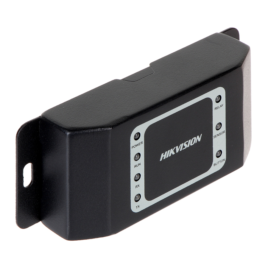
Page 9: Introducing Indicators
Secure Door Control Unit www.hikvision.com Introducing Indicators The Indicators of DS-K2M060 Secure Door Control Unit are POWER, RUN, RX, TX, RELAY, SENSOR and BUTTON. The following tables introduce the meaning of different indicator’s status: POWER: Solid Red The unit is powered on. - Page 10 Secure Door Control Unit www.hikvision.com BUTTON – Indicate the Exit button The green light is on when press the Exit button. When release the button, the green light will be off. Green Notes: Make sure the unit is powered on.
-
Page 11: Chapter 2 Installation
Secure Door Control Unit www.hikvision.com Chapter 2 Installation Introduction of DIP Switch For the DIP switch position, please refer to No.3 of Table 2.1 Description of Rear View. The DIP switch module is shown below. The number of DIP switch from left to right is 1 to 4. - Page 12 Secure Door Control Unit www.hikvision.com Figure 2. 2 DIP Switch Module (Binary Code: 0011) The DIP switch in the secure door control unit is for the RS-485 communication. The code range is from 1 to 15, namely the binary code range between 0001 and 1111. The code cannot be repeated.
-
Page 13: Wiring Cables
Secure Door Control Unit www.hikvision.com Wiring Cables Purpose: Wire cables between Access Control Terminal, Secure Door Control Unit and the lock input/output devices (Wiring to the Wiegand card reader is optional.) to establish the communication between them. Steps: Set the DIP switch code. The binary code range is between 0001 and 1111. - Page 14 Secure Door Control Unit www.hikvision.com Cable Group Color Name Descriptions Green/Brown DOOR_SENSOR Sensor Input Black Green/Black DOOR_BUTTON Door Button Black White/Purple RELAY_NC White/Black RELAY_COM Lock Output White/Red RELAY_NO Yellow RS485 + Black RS-485 Blue RS485 - Figure 2. 4 Rear View of Secure Door Control Unit...
- Page 15 Secure Door Control Unit www.hikvision.com Plug the Wiegand Terminal 2 to the Wiegand as shown in Figure 2.5 and Figure 2.6. The Interface 2 represents the Wiegand interface. Figure 2. 5 Terminals 2 The table displayed below shows the terminal 2 descriptions: Table 2.
- Page 16 Secure Door Control Unit www.hikvision.com Interface 2 Figure 2. 6 Rear View of Secure Door Control Unit...
-
Page 17: Installing Secure Door Control Unit
Secure Door Control Unit www.hikvision.com Installing Secure Door Control Unit Steps: Drill holes on the wall or other places according to the mounting template. Note: The minimum bearing weight of the wall or other places should be three times heavier than the device weight. - Page 18 Secure Door Control Unit www.hikvision.com Figure 2. 7 Fix on the Wall...
-
Page 19: Chapter 3 Wiring External Device
Secure Door Control Unit www.hikvision.com Chapter 3 Wiring External Device The figure displayed below is the wiring introduction of external device: Figure 3. 1 External Device Wiring 0100001060602... - Page 20 Secure Door Control Unit www.hikvision.com...
Need help?
Do you have a question about the DS-K2M060 and is the answer not in the manual?
Questions and answers