Table of Contents
Advertisement
Quick Links
Advertisement
Table of Contents

Subscribe to Our Youtube Channel
Related Manuals for HIKVISION DS-2TD6537T-50H4LX/W


Summary of Contents for HIKVISION DS-2TD6537T-50H4LX/W
- Page 1 xplosion-Proof Thermal Bi-Spectrum Network Positioning System Quick Start Guide...
- Page 2 WARRANTIES, EXPRESS OR IMPLIED, INCLUDING WITHOUT LIMITATION, MERCHANTABILITY, SATISFACTORY QUALITY, OR FITNESS FOR A PARTICULAR PURPOSE. THE USE OF THE PRODUCT BY YOU IS AT YOUR OWN RISK. IN NO EVENT WILL HIKVISION BE LIABLE TO YOU FOR ANY SPECIAL, CONSEQUENTIAL, INCIDENTAL, OR INDIRECT...
- Page 3 Thermal Network Positioning System· Quick Start Guide MANNER THAT DOES NOT INFRINGE ON THE RIGHTS OF THIRD PARTIES, INCLUDING WITHOUT LIMITATION, RIGHTS OF PUBLICITY, INTELLECTUAL PROPERTY RIGHTS, OR DATA PROTECTION AND OTHER PRIVACY RIGHTS. YOU SHALL NOT USE THIS PRODUCT FOR ANY PROHIBITED END-USES, INCLUDING THE DEVELOPMENT OR PRODUCTION OF WEAPONS OF MASS DESTRUCTION, THE DEVELOPMENT OR PRODUCTION OF CHEMICAL OR BIOLOGICAL WEAPONS, ANY ACTIVITIES IN THE CONTEXT RELATED TO ANY NUCLEAR...
- Page 4 Thermal Network Positioning System· Quick Start Guide your supplier or to a designated collection point. For more information see: www.recyclethis.info. Intended use of the camera Ex mark: Hazardous Area Classification: Zone 1, Zone 2, Zone 21, Zone 22. IP Degree: IP68 (2m, 2h) Ex Standards: IEC 60079-0: 2017 EN IEC 60079-0: 2018...
- Page 5 Thermal Network Positioning System· Quick Start Guide This device meets the CAN ICES-3 (A)/NMB-3(A) standards requirements. Safety Instruction These instructions are intended to ensure that user can use the product correctly to avoid danger or property loss. The precaution measure is divided into Warnings and Cautions: Warnings: Neglecting any of the warnings may cause serious injury or death.
- Page 6 Thermal Network Positioning System· Quick Start Guide Cautions To ensure explosion-proof performance, do not damage explosion-proof surface Do not drop the device or subject it to physical shock. Wipe the device gently with a clean cloth and a small quantity of ethanol, if necessary.
- Page 7 Thermal Network Positioning System· Quick Start Guide...
-
Page 8: Table Of Contents
Thermal Network Positioning System· Quick Start Guide Table of Contents 1 Introduction ....................1 1.1 Overview ........................1 1.2 Model Description ....................1 2 Preparation ....................4 3 Appearance Description ................5 3.1 Positioning System Appearance ................5 3.2 Cable Descriptions ....................5 3.3 Alarm In/Out Connections .................. -
Page 9: Introduction
Thermal Network Positioning System· Quick Start Guide 1 Introduction 1.1 Overview Explosion-Proof Thermal Bi-spectrum Network Positioning System is a surveillance product capable of video/audio collecting, smart encoding and network transmitting. It adopts an embedded system and a high-performed hardware process platform to achieve good stability and reliability. - Page 10 Stands for Thermal camera module component performance T: Accurate temperature measurement Max. Resolution (MP): 6: 0.3 MP For specialized application Shape: 6: Positioning System Thermal camera Hikvision front-end product Figure 1-1 Model Explanation Models: DS-2TD6566T-25H2LX/V2, DS-2TD6566T-50H2LX/V2, DS-2TD6566T-25H2LX/V2UHK, DS-2TD6566T-25H2LX/V2CKV, DS-2TD6566T-25H2LX/V2UVS, DS-2TD6566T-25H2LX/V2KVO, DS-2TD6566T-25H2LX/V2HUN, DS-2TD6566T-50H2LX/V2UHK,...
- Page 11 DS-2TD6566T-75H2LX/ V2, DS-2TD6536T-AH2LX/ V2, DS-2TD6566T-AH2LX/ V2, DS-2TD6536T-BH2LX/ V2, DS-2TD6566T-BH2LX/ V2, DS-2TD6536T-CH2LX/ V2, DS-2TD6566T-CH2LX/ V2, DS-2TD6536T-DH2LX/ V2, DS-2TD6566T-DH2LX/ V2, DS-2TD6537T-9H4LX/W, DS-2TD6567T-9H4LX/W, DS-2TD6537T-15H4LX/W, DS-2TD6567T-15H4LX/W, DS-2TD6537T-25H4LX/W, DS-2TD6567T-25H4LX/W, DS-2TD6537T-50H4LX/W, DS-2TD6567T-50H4LX/W, DS-2TD6537T-75H4LX/W, DS-2TD6567T-75H4LX/W, DS-2TD6537T-AH4LX/W, DS-2TD6567T-AH4LX/W, DS-2TD6537T-BH4LX/W, DS-2TD6567T-BH4LX/W, DS-2TD6537T-CH4LX/W, DS-2TD6567T-CH4LX/W, DS-2TD6537T-DH4LX/W, DS-2TD6567T-DH4LX/W, DS-2TD65AD-Q, DS-2TD65AD-W, DS-2TD65AD-E, DS-2TD65AD-R...
-
Page 12: Preparation
Thermal Network Positioning System· Quick Start Guide 2 Preparation Basic Requirement All the electronic operation should be strictly compliance with the electrical safety regulations, fire prevention regulations and other related regulations in your local region. Check the package contents and make sure that the device in the package is in good condition and all the assembly parts are included. -
Page 13: Appearance Description
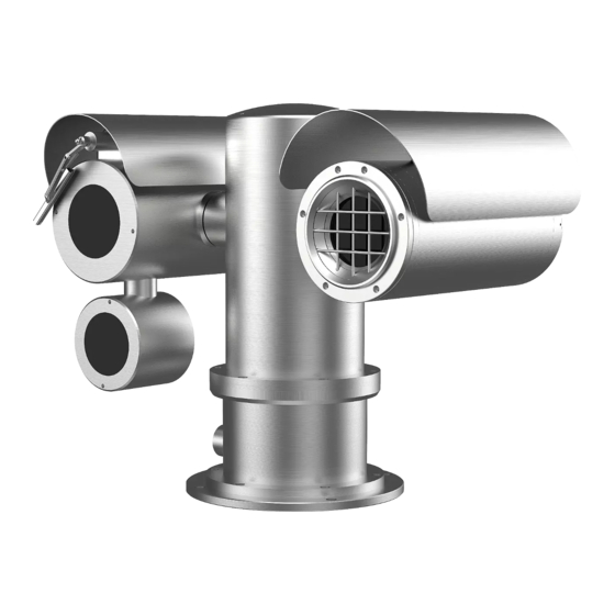
Thermal Network Positioning System· Quick Start Guide 3 Appearance Description 3.1 Positioning System Appearance Refer to the following figures for thermal positioning system overview. Figure 3-1 Thermal Positioning System Overview Table 3-1 Description of Thermal Positioning System Description Optical IR Light Power Cable Thermal 3.2 Cable Descriptions... -
Page 14: Alarm In/Out Connections
Thermal Network Positioning System· Quick Start Guide Figure 3-2 Cables of Positioning Systems 3.3 Alarm In/Out Connections This section is only for the positioning system with alarm in/out functions. The positioning system can be connected with alarm inputs (0~5VDC) and alarm outputs. Refer to the following diagrams for alarm output: JQC- 3FG GND OUT... - Page 15 Thermal Network Positioning System· Quick Start Guide For AC power supply, the external relay must be used (right diagram) to prevent damages to the positioning system and avoid risk of electric shock.
-
Page 16: Installing The Positioning System
Thermal Network Positioning System· Quick Start Guide 4 Installing the Positioning System 4.1 Monitoring Distance Range Electric lens is adopted for the thermal channel of positioning system. It supports auto-focus function and remote focus function. For different lens focal length, the monitoring range is shown in the table below: Table 4-1 Monitoring Range (Pixel Interval: 17um) Lens Focal Length/mm... -
Page 17: Bracket Installation
Thermal Network Positioning System· Quick Start Guide Please get familiar with the installation environment before you wiring, including the wiring distance, wiring environment, keeping magnetic-field interference away, etc. Please make sure the rated voltage of the cable is higher than that the device requires, thus guarantee the device can work normally when the voltage instability occurs. - Page 18 Thermal Network Positioning System· Quick Start Guide Figure 1-3 Drill Expansion Screws 4. Align the holes on the bracket with the position of expansion screws, Install the bracket plate onto the wall, and tighten the expansion screws. Figure 1-4 Install Bracket Plate 5.
-
Page 19: Explosion-Proof Tube Installaion (Without Fiber)
Thermal Network Positioning System· Quick Start Guide 4.4 Explosion-proof Tube Installaion (without fiber) : Purpose You must use the explosion-proof tube and junction box to prevent the explosive gas from entering into the camera through the cable. Or it may cause danger. Steps: 1. -
Page 20: Explosion-Proof Control Box(Atex/Iecex Certificates ) Installation (Without Fiber)
Thermal Network Positioning System· Quick Start Guide 4.5 Explosion-proof control box(ATEX/IECEx certificates ) Installation (without fiber) Steps: 1. Attach the junction box onto the wall, and mark the four screw sites with pencil. 2. Drill four φ8 screw holes on the wall. 3. - Page 21 Thermal Network Positioning System· Quick Start Guide Figure 1-9 Disassemble the Junction Box 7. Connect the cables. 1). Route the camera cables through the top cable gland and insert them into the junction box. 2). Route the external cables through the bottom cable gland and insert them into the junction box.
-
Page 22: Explosion-Proof Control Box(Atex/Iecex Certificates ) Installation (With Fiber)
Thermal Network Positioning System· Quick Start Guide Result: The Installation is complete, see the figure below. Figure 1-12 Installation Complete 4.6 Explosion-proof control box(ATEX/IECEx certificates ) Installation (with fiber) For type DS-2TD□TF-□,Refer to Figure 1-13,must use galvanized steel pipe to protect optical fiber strongly. -
Page 23: Finishing Installing
Thermal Network Positioning System· Quick Start Guide Figure 1-13 Installation Complete With Optical Fiber Model 4.7 Finishing Installing Connect the corresponding cables and turn the power on; the system will do the self-test automatically. Make sure the live view image and the PTZ control work normally and then finish the installation. -
Page 24: Setting The System Over The Lan
Thermal Network Positioning System· Quick Start Guide 5 Setting the System over the LAN You shall acknowledge that the use of the product with Internet access might be under network security risks. For avoidance of any network attacks and information leakage, please strengthen your own protection. -
Page 25: Activation Via Sadp Software
Thermal Network Positioning System· Quick Start Guide 6. Power on the system, and connect the system to the network. 7. Input the IP address into the address bar of the web browser, and click Enter to enter the activation interface. The default IP address of the system is 192.168.1.64. -
Page 26: Modifying The Ip Address
Thermal Network Positioning System· Quick Start Guide Select inactive device. Input and confirm password. Figure 5-3 SADP Interface 3. Create a password and input the password in the password field, and confirm the password. STRONG PASSWORD RECOMMENDED– We highly recommend you create a strong password of your own choosing (using a minimum of 8 characters, including upper case letters, lower case letters, numbers, and special characters) in order to increase the security of your product. - Page 27 Thermal Network Positioning System· Quick Start Guide 3. Change the device IP address to the same subnet with your computer by either modifying the IP address manually or checking the checkbox of Enable DHCP. Figure 5-4 Modify the IP Address 4.
-
Page 28: Operating Via Web Browser
Thermal Network Positioning System· Quick Start Guide 6 Operating via Web browser 6.1 Accessing the System System Requirement: Operating System: Microsoft Windows XP SP1 and above version / Vista / Win7 / Server 2003 / Server 2008 32bits CPU: Intel Pentium IV 3.0 GHz or higher RAM: 1G or higher Display: 1024×768 resolution or higher Web Browser: Internet Explorer 7.0 and above version, Apple Safari 5.02 and above... -
Page 29: Live View Page
Thermal Network Positioning System· Quick Start Guide Figure 6-1 Login Interface 5. Install the plug-in before viewing the live video and managing the network positioning system. Please follow the installation prompts to install the plug-in. You may have to close the web browser to finish the installation of the plug-in. Figure 6-2 Download Plug-in 6. - Page 30 Thermal Network Positioning System· Quick Start Guide Menu Bar PTZ Control Show or hide PTZ control panel Live View Window Live View Parameters Toolbar Preset/ Patrol/ Pattern Figure 6-3 Live View Page Menu Bar: Click each tab to enter Live View, Playback, Picture, and Configuration page respectively.
-
Page 31: Appendix
Thermal Network Positioning System· Quick Start Guide Appendix Frequently Asked Questions (FAQ) Device Running Error Question: The device fails to start up or reboots repeatedly. The device constantly powers off unexpectedly when you pan/tilt the device or call preset. ... - Page 32 Thermal Network Positioning System· Quick Start Guide Live view fails with good network connection. Answer: Examine if the IE plug-in is well installed. Change the Website Blocker settings if necessary. For cross-domain routing, enable the UPnP of device, or set manual mapping to port No.
-
Page 33: Common Material Emissivity Reference
Thermal Network Positioning System· Quick Start Guide Common Material Emissivity Reference Material Emissivity Human Skin 0.98 0.91 Cement Concrete 0.95 Ceramics 0.92 Rubber 0.95 Paint 0.93 Wood 0.85 Asphalt 0.96 Brick 0.95 Sand 0.90 Soil 0.92 Cotton 0.98 Cardboard 0.90 White Paper 0.90 Water... - Page 34 UD25684B-A...
Need help?
Do you have a question about the DS-2TD6537T-50H4LX/W and is the answer not in the manual?
Questions and answers