
Related Manuals for HIKVISION Pyronix EURO 46 V10


Summary of Contents for HIKVISION Pyronix EURO 46 V10
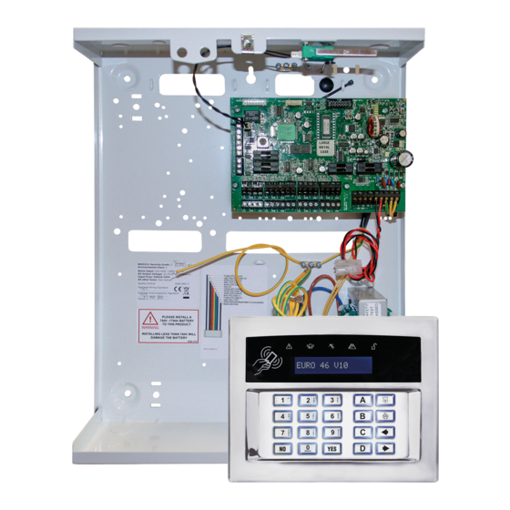
- Page 1 EURO 46 V10 Programming Manual PD6662:2010+IA501:2015 EN50131-1:2008+A1:2009 EN50131-3:2009 Security Grade (SG) 3 - Large Security Grade (SG) 2 - Small Environmental Class (EC) II Software Version >10 RINS1942-1...
-
Page 2: Table Of Contents
Contents Introduction PyronixCloud and HomeControl+ App Engineer Menu - Navigation Navigating in the Engineer and User Menus Main Menus and Sub-menus Entering The Engineer Menu Exiting The Engineer Menu Accessing the Engineers Menu on any Keypad Saving The Programming Writing Text on the keypad Misc Button Typing Engineer Menu - Options Inhibit Fire / HU (Hold Up) - Page 3 Appendix 1 - Input Types Appendix 2 - Output Types Appendix 3 - SMS Commands Appendix 4 - Factory Defaults Appendix 5 - Event Types (SIA and Contact ID codes) EURO 46 V10 Programming Manual...
-
Page 4: Introduction
Introduction This EURO 46 V10 has been designed with security in mind, quick and easy installation and minimal maintenance, this system protects properties with a multitude of unique features. As well as wired, this system can take full advantage of innovative two way wireless technology, with the wireless devices on this system constantly communicating with each other using High Security Wireless Encryption Protocol. -
Page 5: Pyronixcloud And Homecontrol+ App
PyronixCloud and HomeControl+ App Connect to your home from anywhere in the world Set and unset your system View your system status in real time, including: alarm, CO and smoke detectors Customise and receive push notifications from your system Have instant access to your events and history log Control appliances such as lights, garage doors, gates and blinds All using an encrypted, highly secure system, for extra peace... -
Page 6: Engineer Menu - Navigation
Engineer Menu - Navigation The system is programmed from the Engineer Menu. To enter the Engineer Menu the panel must be in an unset state. While the panel is in Engineer Menu all tamper alarms (including case tamper), will be disabled. Navigating in the Engineer and User Menus ... -
Page 7: Accessing The Engineers Menu On Any Keypad
Accessing the Engineers Menu on any Keypad It is possible to access the Engineer Menu on any keypad that is part of the system, even when another keypad is already in the Engineers Menu. All other keypads will display ‘System Busy’ where a keypad is in the Engineer Menu. -
Page 8: Engineer Menu - Options
Engineer Menu - Options Inhibit Fire / HU (Hold Up) This menu has a single sub-menu that simply allows you to toggle between ‘Yes [1]’ and ‘No [0]’, in order to Inhibit a fire or Hold Up alarm while in engineer’s mode/menu. For example, you may wish to inhibit smoke detectors while in the engineers menu so that you can work on them. - Page 9 Press and hold the ‘learn’ button on the device and all three LEDs start cycling through. Release the ‘learn’ button. If successful, ‘Input Learnt’ will be displayed on the keypad and a confirmation tone will be emitted. If that input has already been learnt, ‘Input learnt already’ will be displayed. To locate the learn button on each wireless peripheral, please refer to the installation manual provided with the device.
- Page 10 Control Arming Stations? Learn Devices? Entering this menu allows the learning of wireless arming stations onto the system. Select Arming Station Selects the arming station on the system that is to be learnt. ‘Learnt’ will be displayed if an arming station is already learnt, or ‘Available’...
- Page 11 Proceed with the programming of actions to each key. Delete/Change User (Key fobs) Enter Master Manager menu (press the d Key then enter code). Scroll to the function ‘EDIT USERS?’. Select ‘Delete/Change User?’ Choose the key fob to delete = Between the brackets will show [******]. Press c = The brackets will be showing [ ] to confirm the deletion.
-
Page 12: Change Inputs
Change Inputs? By default, all inputs are set to ‘unused’. Before programming, identify the input type required: PLEASE NOTE: A full list of all input types can be found in ‘Appendix 1’. Choose Input Choose an input to program. Input Type: Assign an input type to the chosen input. For a full list of input types, please refer to ‘Appendix 1’. -
Page 13: Choose Mode
Attribute Operation for both wired and wireless inputs Confirm Group If inputs are selected into the same confirm group, each input will only generate an unconfirmed alarm (and will not generate a confirmed activation). This is useful when two or more shock sensors are being activated by the same event. -
Page 14: Install Zems
Choose Mode Programming Press b or to scroll to ‘CHOOSE MODE’. Press . CHOOSE MODE? Press b or d to select the ‘EOL Range’ for all wired inputs*, Then press . EOL Range 4K7/2K2 Press b or d to select the ‘EOL Mode’ for all wired inputs. -
Page 15: Change Outputs
Press to return to the Engineers menu. PLEASE NOTE: If using wireless bells, Wireless Arming Stations or key fobs, the wireless ZEM has to be addressed as 00. Change Outputs? This option enables the programming of the outputs on the EURO 46 V10 and any devices that are connected to it. - Page 16 Type The device types that are available will depend upon the selected address: LCD keypads [0], Readers [1] Not Used [2], Arming Stat [3] Reader is If a reader is installed, the following options can be assigned to the reader: [0] Set Point: Reader used for setting and unsetting.
- Page 17 ‘Enter Location’ will be displayed. Enter the location of the keypad and press . Enter Location 10. Press b or d to select another device address to program (0-9) or press the key to return to the Engineer Menu. Programming Readers for Set Point or Unset Only: Assign Keypads/Readers Press b or ...
- Page 18 11. Press b or d to select another device address to program (1-7) or press the key to return to the Engineer Menu. Programming Readers for Entry Control or Access Control: Assign Keypads/Readers Press b or to scroll to ‘ASSIGN KEYPADS/ READERS’.
- Page 19 12. ‘Enter Name’ will be displayed. Enter the name of the keypad and press . Enter Name Device 01 13. ‘Enter Location’ will be displayed. Enter the location of the keypad and press . Enter Location 14. Press b or d to select another device address to program (1-9) or press the ...
-
Page 20: Change Timers
10. ‘Set Point Sets’ will be displayed. Select the area(s). Press . Set Points Sets [01ABCD] 11. ‘Set Point Unsets’ will be displayed. Select the area(s). Press . Set Point Unsets [01ABCD] 12. ‘Set Point In’ will be displayed. Enter the Area in which the Arming Station is situated and press . - Page 21 Timers Description Options The duration of time the strobe output remains live after the bell time ends Strobe Time 0-99 minutes PLEASE NOTE: ‘99’ means endless. The number of times the system re-arms after the confirmation time ends. Re-arm number Re-Arm No.
-
Page 22: Codes And Users
Codes And Users? Five Digit PINs? Set this option to ‘Yes’ to allow the use of 5 digit and 6 digit codes (This will disable codes below 5 digits in length). Set this to ‘No’ if you would prefer to use codes below 5 digits in length. Delete Users And Fobs? This function deletes all the user codes (or tags/fobs assigned to a user) from the system. -
Page 23: Volume Control
The LCD will now display ‘Delete Users And Fobs?’. Press and ‘Are you Sure?’ will be asked. Press to delete all users or to go back. Change Duress Codes? PLEASE NOTE: This is not reversible. ‘Change Duress Codes’ will be displayed. Press to add any Duress, Guard or Dial out codes or press . -
Page 24: System Options
Entry/Exit Keypads Only If this function is disabled, any entry and exit tones will be heard through the main sounder. If enabled, the entry and exit tones will only be heard through the keypad speaker. Alert Kps Only If this function is enabled, any ‘Alert’ tones will be heard on the keypad only and not the main sounder. - Page 25 Option Description If ‘Yes’, this will automatically prioritise the exit modes for each area: (0 = Timed, 1 = Final Door, 2 = Timed/Final Door, 3 = PTS). This option is only relevant when Final Door option is used on a system with different areas using a common lobby. Common Lobby? EXAMPLE: If Area C is selected as the ‘Final Door’...
-
Page 26: Review Logs
If 'Yes’, then the keypad display will show any inputs that are activated in unset mode. Display Inputs PLEASE NOTE: This must be programmed as ‘No’ to ensure compliance with EN 50131. Exit Modes Exit Mode Description Providing that all inputs are closed, the system will only set when the programmed 'Exit Time' has [0] Timed expired. - Page 27 first detector. It is also possible to walk test a single input by pressing when the keypad displays ‘Walk Test Areas?’ Soak Control Any input may be placed on ‘soak test’ to prevent it from generating an alarm. If the input triggers while the system is set, it will indicate the activation and enter the details in the system log.
-
Page 28: Diagnostics
Diagnostics? This option enables the engineer to perform full diagnostics on all key wired and wireless components of the system. Wireless Devices View Inputs: This option views the status of all wireless inputs: O=Open, C=Closed, T=Tamper, B=Battery and S=Supervision. View Inputs / Bells Signal Strength: This option is used to view the signal strength for any wireless input, bell or arming station that is learnt to the system. - Page 29 Wireless Dual Frequency Menu: This option is used to view and troubleshoot the Dual Frequency operation of your system: Channel – Displays which channel your control panel is operating on (this will be either 01 or 02). Channel Reason – Displays the reason why the panel last switched from one channel to another. SF/DF Status –...
- Page 30 Communications This function displays the information gathered from the communication device currently fitted. GPRS Module: GPRS Signal Strength: The range ‘0-31’ indicates the signal (31 = Excellent. <15 = Poor). ‘--.-- ‘ indicates no signal. App or ARC Status messages: Displays the current connection status of the PyronixCloud. •...
-
Page 31: Engineer Restore Options
Engineer Restore Options? Restore Option Effect Engineer Restore Intruder If 'Yes', then the user code will silence the alarm, but the engineer must reset the system with the Engineer Code before it can be used again. This will not interfere with the generation of HU alarm. - Page 32 Silent 1st Alarm If this function is selected as ‘confirmed’, then the first alarm to be activated on the system will be silent, but if another input activates (i.e. a confirmed alarm) then the alarm tones will be heard. This option is only valid once the system has been set for 3 minutes and if the entry time has not been initiated.
-
Page 33: Set Up Downloading
Day Alarm Starts at: This feature programs the starting point of the alarm responses for a 24 hour alarm. The levels are: ‘Keypads’, ‘Internal Sounders’, ‘Sirens Only’ and ‘Digi’. Day Alarm Stops at: This feature programs the ending point of alarm responses for a 24 hour alarm. Chose from: ‘Keypads’, ‘Internal’... -
Page 34: Software Revision
Software Revision? This option shows the software version, hub version and communication module version installed in the panel. Please obtain the software version number prior to contacting customer support, so that the correct information can be given upon supporting the product. Clean Start? This option is used to default the settings on the panel. -
Page 35: Wired Keypad Menu
Wired Keypad Menu The keypads have a small internal menu used mainly for: addressing, changing the key click volume and changing the brightness of the LCD display. Entering and Exiting the Keypad Menu To enter the Keypad Menu, press and hold the d button until ‘SECURITY CODE:’ is displayed, enter ‘2000’. -
Page 36: Connecting To Insite Software
Connecting to InSite Software The Control Panel can be programmed by the LCD menu or the UDL InSite Software (provided free of charge). It can be downloaded from http://www.pyronix.com/pyronix-downloads.php. The connection between the control panel and the UDL software can be done in the following ways: Cloud Connection On the Panel Enter the Engineer Menu. - Page 37 Serial Connection (RS232) The Control Panel is set up by the factory with the RS232 port enabled as a method to connect to the UDL software. PLEASE NOTE: For this connection a special cable (that is supplied by Pyronix) is required, or it can be created according to the diagram on the right.
-
Page 38: Options Programmable Only From Pc
Options Programmable Only From PC The UDL software is available on www.pyronix.com/downloads. The software can be used to upload/ download to the Control Panel and data can be viewed. Two features that the UDL software incorporates are: • Auto Set and Unset Timer •... -
Page 39: Areas To Set/Unset
Areas to Set/Unset This section of the software selects the areas that will be Set/Unset during the ‘Auto Set/Unset’ period. Select the areas to be set and type them in the ‘Areas’ field. Select the ‘Warning Period’. This is a time (in minutes) when the Panel will warn anyone who may be in the premises that an Auto-Set is about to take place. -
Page 40: Faults And Troubleshooting
Faults and Troubleshooting Device Fail / Active Faults If a device on the system is not installed correctly or has been lost from the bus, a device fail will be present. An example of each fault is as follows: • Failure on the panel = ‘Control Panel, Wireless Jamming Pnl’... - Page 41 Fault Description Solution KEYS LOCKED OUT a) More than one device is connected at the same a) Ensure correct addressing so that there are no address. overlaps. Next, power the system down and back up again to correctly reinitialise. b) Too many incorrect key presses have been entered to create a ‘Code Guessing’...
-
Page 42: Access Levels
Fault Description Solution I-01 (xx) Low battery on wireless input number ‘xx’ Replace the battery on the input device mentioned. WLs LOW BATT B-01 (xx) Low battery on wireless siren number ‘xx’ Replace the battery on the radio siren mentioned. WLs LOW BATT I-01 (xx) Device on wireless input number ‘xx’... - Page 43 Appendix 1 - Input Types Input Types Operation Unused Factory default. Input is disabled. Active at all times. Audible Response: Differentiated Internal sound. Pulsed external sound. Fire Communicator: ‘Fire’ signal Active at all times. Audible Response: Full external + Internal sound. Communicator: ‘Gas’...
- Page 44 Input Types Operation Active when system set. Works in conjunction with EE input type for detection of forced entry. This input type is designed specifically for use with systems installed using BS8243 option 6.4.5. This input type is always used in conjunction with an ‘Entry/Exit’ input. The ‘Entry/Exit’ input is a door contact on the initial entry door, and the ‘Entry Shock’...
- Page 45 Appendix 2 - Output Types Output Type Active Restore 0000 Not Used 0001 Fire At a fire alarm activation. When a valid code is entered. 0002 Hold Up Any At a hold up (HU) /personal attack activation. When a valid code is entered. 0003 Intruder Any At an intruder alarm from any area.
- Page 46 Output Type Active Restore 0034 Lights When the exit or entry timer starts. 20 seconds after the set/unset procedure has completed. 0035 Follow Input • Active when a specific input number has been activated. It allows the following options to be programmed: •...
- Page 47 Output Type Active Restore 0065 Zone Activity Fault This is the output that will activate in response to the ‘Monitor Activity’ Input, once the programmed NAT time has elapsed. It will be cleared / restored by the next valid code entry. 0066 ATE Not Used Makes the ATE pin 5V or 0V depending on whether ATE outputs are inverted.
- Page 48 Appendix 3 - SMS Commands Setting the system via SMS text command Example SMS command send: Description: Example SMS command response: 123456 Set A 123456 = User Code. Set A = Will set the Enforcer in area A. Final Set; area A 123456 Set ABCD 123456 = User Code.
- Page 49 NOTE: The user automation outputs can be also activated via the keypad or the key fob. NOTE: The name of the output has to be one word and spelled exactly as written in the panel, such as: ‘Garage Door’ is not acceptable.
- Page 50 Appendix 4 - Factory Defaults Defaults Engineer Menu Sub-Menu 2000 2002 Differences INHIBIT FIRE/HU? Inhibit Fire/HU No [0] SET DATE & TIME? Year (00-99) [07] Month (1-12) [01] Day (1-31) [01] Hours (0-23) [00] Minutes (0-59) [00] DST Adjust? No [1] WIRELESS DEVICE CONTROL? Inputs 9 - 32 Available...
- Page 51 Defaults Engineer Menu Sub-Menu 2000 2002 Differences ATE Pin 3 Unconfirmed Any [0018] ATE Pin 4 Final Set All [0004] ATE Pin 5 Tamper Any [0007] ATE Pin 6 Omit Rearm Any [0017] ATE Pin 7 Confirmed Any [0006] ATE Pin 8 Mains Fail [0052] ATE Pin 9 Global Fault 2 [0056]...
- Page 52 Defaults Engineer Menu Sub-Menu 2000 2002 Differences Guard Code Alarm [03] (minutes) Fire Siren Time [99] (minutes) Set Fail Warning [00] (minutes) Input NAT Days [14] (days) Input NAT Hours [00] (hours) Wireless Supervision Time [02] (hours) Wireless Jamming Time [100] (seconds) Service Time...
- Page 53 Defaults Engineer Menu Sub-Menu 2000 2002 Differences Confirmed When Final Set [0] Autoset Force No [0] Restrict PIN Use No [0] Simple Set? No [0] Intelligent Set? No [0] Invert ATE O/Ps Yes [1] Common Lobby Yes [1] Flexi Unset? No [0] 2 Key HU None [3]...
- Page 54 Defaults Engineer Menu Sub-Menu 2000 2002 Differences Fetch Time DIAGNOSTICS Wireless Devices Wired Devices Communications ENGINEER RESTORE OPTIONS Engineer Restore Intruder No [0] Engineer Restore HU No [0] Engineer Restore Tamper Yes [1] No [0] Engineer Restore Soak No [0] Engineer Restore Confirm Yes [1] No [0]...
- Page 55 Defaults Engineer Menu Sub-Menu 2000 2002 Differences Digi 07 Confirmed Any [0006] Digi 08 Mains Fail [0052] Digi 09 Global Fault 2 [0056] Global Fault 1 [0055] Digi 10 Test ATS [0064] Digi 11 Not Used [0000] Digi 12 Not Used [0000] Digi 13 Not Used [0000] Digi 14...
- Page 56 Defaults Engineer Menu Sub-Menu 2000 2002 Differences HU Starts at Digi [3] Hu Stops at Confirm [4] Medical Starts, stops Digi [3] Day alarm starts, stops Sirens Only [2] Start at, Stop at Digi [3] If area set [------] SET UP DOWNLOADING? Download by None [0] Security Level...
- Page 57 Appendix 5 - Event Types (SIA and Contact ID codes) Event Event Type Default 1 Default 2 Default 3 Default code code Number (ARC) (ARC) (ARC) (SMS) Full No Arm/ No Arm/ Reporting Disarm Disarm and Alarm Restores Auto Set 3403 Forced Set 3401...
- Page 58 Event Event Type Default 1 Default 2 Default 3 Default code code Number (ARC) (ARC) (ARC) (SMS) Full No Arm/ No Arm/ Reporting Disarm Disarm and Alarm Restores FIRE ALARM Fire Alarm 1110 Fire key pressed 1110 FIRE ALARM RESTORE Fire Alarm Restore 3110 Fire key Restore...
- Page 59 Event Event Type Default 1 Default 2 Default 3 Default code code Number (ARC) (ARC) (ARC) (SMS) Full No Arm/ No Arm/ Reporting Disarm Disarm and Alarm Restores OMIT Zone Omitted 1570 Zone Force (Omitted) Set 1570 Fire Zone Omitted 1571 Day Alarm Zone Omitted 1572...
- Page 60 Event Event Type Default 1 Default 2 Default 3 Default code code Number (ARC) (ARC) (ARC) (SMS) Full No Arm/ No Arm/ Reporting Disarm Disarm and Alarm Restores WIRELESS ALARM/RESTORE Radio low battery 1384 Radio supervision failure 1381 Radio hub jamming 1344 Radio hub jam restore 3344...
- Page 61 Event Event Type Default 1 Default 2 Default 3 Default code code Number (ARC) (ARC) (ARC) (SMS) Full No Arm/ No Arm/ Reporting Disarm Disarm and Alarm Restores INFORMATION Engineer Access 1627 Engineer Exit 1628 System Restart 1305 Logs Cleared 1621 Engineer Reset 3313...
- Page 62 EURO 46 V10 Programming Manual...
- Page 63 EURO 46 V10 Programming Manual...
Need help?
Do you have a question about the Pyronix EURO 46 V10 and is the answer not in the manual?
Questions and answers