Table of Contents
Advertisement
Quick Links
Advertisement
Table of Contents

Related Manuals for HIKVISION DS-PF-E0204 Series


Summary of Contents for HIKVISION DS-PF-E0204 Series
- Page 1 Energizer Product Instruction...
- Page 2 DS-PF-E0204 Series Energizer User Manual Thank you for purchasing our products, if you have any questions or needs, please don't hesitate to contact us. This manual applies to the following products: Product Model Product Name DS-PF DS-PF-E0204 This manual may contain technical inaccuracies or inconsistencies with product features and operations, or typographical errors.
- Page 3 DS-PF-E0204 Series Energizer User Manual Conventional Symbols The following symbols may appear in this document, and their meanings are as follows. Symbol Description Indicates a medium or low level of potential danger that, if not avoided, could result in minor or moderate injury.
- Page 4 DS-PF-E0204 Series Energizer User Manual Attentions ● Do not drop any objects on the equipment or shake it vigorously. Keep the equipment away from locations with magnetic interference. Avoid installing the equipment where the surface is shocked or subject to shock. (The equipment may be damaged if ignoring this item) ●...
-
Page 5: Table Of Contents
DS-PF-E0204 Series Energizer User Manual Contents Chapter 1 Introduction to the DS-PF-E0204 Series Series Energizer....05 1.1 Product Introduction ..................... 05 1.2 Functional characteristics ..................06 1.3 How it works ....................... 07 1.4 Product structure ....................08 1.4.1 Description of the equipment panel .............. -
Page 6: Chapter 1 Introduction To The Ds-Pf-E0204 Series Series Energizer
DS-PF-E0204 Series Energizer User Manual Chapter 1 Introduction to the DS-PF-E0204 Series Energizer 1.1 Product Overview As a kind of perimeter barrier prevention alarm system, Electric Fence is a "visible" alarm system that introduces the latest international alarm concept of "Barrier-based supplemented by the alarm."... -
Page 7: Functional Characteristics
DS-PF-E0204 Series Energizer User Manual 1.2 Functional characteristics ● 4.3-inch LCD display operation screen ● The operating voltage value for each zone is displayed ● Voltage can be steplessly regulated (0.9kV-6.5kV) ● The operating current value for each zone is displayed ●... - Page 8 DS-PF-E0204 Series Energizer User Manual 1.3 Working principle Electronic fence system is usually composed of energizer and front-end fence, which can be linked to closed-circuit CCTV monitoring, Internet transmission, virtual matrix and integrated monitoring software. The front-end fence contains a physical barrier and a dedicated electronic fence.
-
Page 9: Product Structure
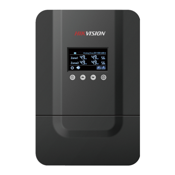
DS-PF-E0204 Series Energizer User Manual 1.4 Product structure 1.4.1 Description of the equipment panel Run status display Energizer runtime display Zone voltage and current display Zone alarm display Setup Down Power button... -
Page 10: Description Of The Internal Wiring Terminals
DS-PF-E0204 Series Energizer User Manual 1.4.2 Description of the internal wiring terminals Internal schematic diagram of DS-PF-E0204: Auxiliary output battery Address code Integrated on-off alarm output Press from “1” Anti zone 2 zone 1 demolition alarm alarm alarm output output... -
Page 11: Chapter 2 Technical Specifications Of Ds-Pf-E0204 Series Series Energizer
DS-PF-E0204 Series Energizer User Manual Chapter 2 DS-PF-E0204 Series Energizer Specifications DS-PF-E0204 Model Number of Dual zone zones Recommended 4 lines, 8 lines line Indication LCD screen ≥ 1S Pulse period ≤ 0.1S Duration Flame UL94V-0 retardant factor The current <10A... -
Page 12: Chapter 3 Use And Installation
DS-PF-E0204 Series Energizer User Manual Chapter 3 Use and Installation 3.1 Equipment packaging and visual inspection ● Before use, please read the instructions in this manual and pay attention to the considerations of use and installation. ● Appearance should be clean and smooth, the surface has no cracks and permanent stains, and logo is correct. - Page 13 DS-PF-E0204 Series Energizer User Manual 2. Turn the energizer, observe the fixed hole, and then hang it on the fixed screw of the energizer’s fixed plate, as shown in the Figure: HIKVISION 3. Installation complete: HIKVISION...
-
Page 14: Energizer Wiring Diagram
DS-PF-E0204 Series Energizer User Manual 3.3 Energizer wiring diagram DS-PF-E0204 energizer wiring diagram: HIKVISION F1 F2 F3 F4 R1 R2 R3 R4 Ground Ground Ground Description ● Connect the high-voltage insulated conductor of the energizer to the front-end fence through PVC wiring tube. Wire connector (or self-winding) should be used for reliable connection. -
Page 15: Installation Of Siren
DS-PF-E0204 Series Energizer User Manual 3.4 External equipment installation instructions 3.4.1 Installation of siren Positive pole of 12V power adapter is connected with the same end of the Siren, negative is connected with COM terminal of the alarm output relay in the... -
Page 16: Chapter 4 Operating Instructions Of The Energizer
DS-PF-E0204 Series Energizer User Manual Chapter 4 Operating Instructions for the Energizer 1. Connect the line and turn on the power, then the energizer's LCD screen lights up, indicating that the energizer power is normal. 2. Press the power button at the bottom of the energizer to switch its working state (arm or disarm). -
Page 17: Chapter 5 Front-End Fence Installation
DS-PF-E0204 Series Energizer User Manual Chapter 5 Front-end Fence Installation Manual Note: Do not install electronic fence products outdoors in thunderstorms. Before installation, please carefully check the product appearance and supply list, and offer a training of security operation skills to installers. - Page 18 DS-PF-E0204 Series Energizer User Manual Product knowledge Front fence composition: Tensioner Joint Clamp General Post General Post Cap Insulator General Post Cap General Post Insulator General Post Base Frame Screw ( for Knighthead) General Post Base Frame Screw ( for Security Post)
- Page 19 DS-PF-E0204 Series Energizer User Manual Generic Cabling System The electronic fence system is composed of front-end fence, energizer, back-end control part and other linkage equipment. The pulse host is the core of the control, transmission and detection of the electronic fence system. it provides the pulse voltage to the front fence through the high-voltage insulated wire, and transmits the alarm signal to the back-end control part for management.
- Page 20 DS-PF-E0204 Series Energizer User Manual Diagram of GCS...
- Page 21 DS-PF-E0204 Series Energizer User Manual Installation of Front End Fence This chapter mainly introduces the composition and installation skills of front end fences. Please make an appropriate adjustment according to the field situation. Structure of front end fence Waterproof Box...
- Page 22 DS-PF-E0204 Series Energizer User Manual Installation steps: User Ma n ual ① security post (exemplified by four wire security post): General Post Cap×1 For screws×2 General Post Base Frame ( for Security Post) ×2 1. Accessories of Security Post General Post Insulator×4 Screw×4...
- Page 23 DS-PF-E0204 Series Energizer User Manual Knighthead (exemplified by four wire knighthead): ② General Post Cap×1 General Post Insulator×4 Screw×4 Accessories of For screws×2 knighthead General Post Base Frame ( for Knighthead) ×1 Expansion screw(Customer General Post self provided General Post Cap Fixed general post and for screws.
- Page 24 DS-PF-E0204 Series Energizer User Manual ④ High Conductivity Wire 1. Install high conductivity wire after all the posts are installed. 2. Install high conductivity wire with general post insulator and joint clamp at the same time. The high conductivity wire starts from end post insulators. It is reserved for 10 cm on the one side, wounding on the high conductivity wire after through the hole on the insulator (attention to beauty while wounding and no less than 5 rings), and then connects with joint clamp.
- Page 25 DS-PF-E0204 Series Energizer User Manual Unscrew the upper two nuts on the high conductivity wire, tighten the first nut, and then tighten the second one. ⑥ Strainer Tensioner be placed during the installation of end posts to tighten the high conductivity wire between two end posts.
- Page 26 DS-PF-E0204 Series Energizer User Manual The ground pile should be driven deep into the underground 1.5m. The grounding wire should be used yellow and green wire, recommended 8mm wires or above the recommended specifications. Connect to the upper- most wire of the front end.
- Page 27 DS-PF-E0204 Series Energizer User Manual ⑨ Warning signs The warning sign of “High Voltage No Climbing” should be installed every 10 meters on the top line of high conductivity wire and fixed on with soft metals. Remember to fix the three holes on the warning sign in case that it sways in the wind.
- Page 28 DS-PF-E0204 Series Energizer User Manual ⑪ Across-the-line fence Across-the-line electric fence include following types: 1. Front across-the-line: it mainly transmits the pulse voltage of energizer to high conductivity wires on the fences. Use insulated cable to lead all the alloy wires on the front end fences to waterproof box and connect with high-voltage output terminals of energizer according to the wiring diagram.
-
Page 29: Chapter 6 Frequently Asked Questions
DS-PF-E0204 Series Energizer User Manual Chapter 6 Frequently Asked Questions ● Failure: Continuous alarm of the host Identification: there are open circuit, short circuit and short circuit to ground. Elimination: ① Open circuit of front end: test the loop with a multimeter to determine the failure. - Page 30 DS-PF-E0204 Series Energizer User Manual Elimination: ① Front end: test whether the resistance value of each connector is in a normal range with a multimeter, Otherwise, it should replace the high conductivity wire of fences. At the same time, check whether the wire resistance of insulated cable is too high due to the fracture or high-voltage ignition, if so, the wire should be replaced.
-
Page 31: Appendix: Packing List
DS-PF-E0204 Series Energizer User Manual Appendix: Packing Packing list of energizer List Name of Product Product Screw energizer Power cord item instruction certification accessories Quantity Appendix: Restriction Substance or Element Identification Table Restriction substance or element identification table of RoHS 2.0 Restriction substance or element identification table of RoHS 2.0... -
Page 32: Warranty Service
DS-PF-E0204 Series Energizer User Manual Warranty service Respected Users Thank you for choosing our product. In order to fully enjoy the perfect after-sales service support, please read the instructions of this product warranty card carefully after purchase and keep it properly. - Page 33 DS-PF-E0204 Series Energizer User Manual User name: ________________________________________________________ Address:___________________________________________________ Telephone:____________ Fax:_____________ Zip code:________ E-mail:___________________________________________________ Model:_________________________ S/N:____________________________ Date of manufacture:_______________ Date of purchase:__________________ If you have other requirements, please fill in the following: ___________________________________________________________ ___________________________________________________________ ___________________________________________________________ Distributor:________________ Telephone:_________________...
Need help?
Do you have a question about the DS-PF-E0204 Series and is the answer not in the manual?
Questions and answers