Page 1
Find more online at www.codelockssupport.com 
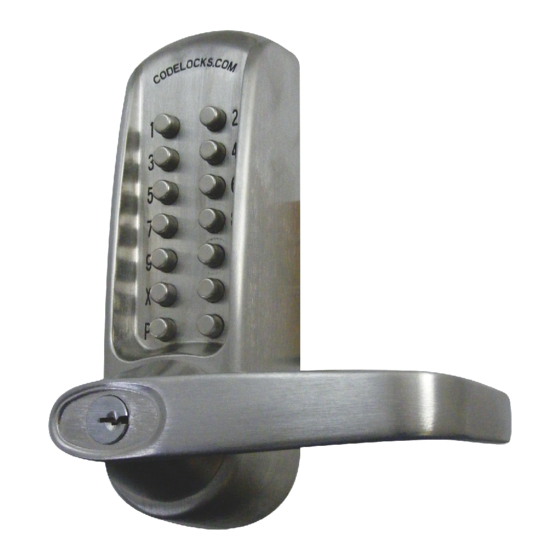
CL600 Installation Instructions Tools Required for installation: Contents • Power drill CHECK THAT THE CONTENTS OF YOUR BOX ARE CORRECT ACCORDING TO THE MODEL • Drill bits 30mm (1 / "), 25mm (1"), 20mm ( / "), 16mm ( / ") &...
Page 2
The code may be entered in any sequence, ie 1370 may be entered as 0731 or any other sequence of those numbers. There are a total of 8,191 codes available on the CL600, CL610 and CL620 locks. There are 4,095 codes available on the CL605, CL615 and CL625 locks.
Page 3
Take the BLUE or RED tipped spindle and fit to the code side according to the hand of your door (see diagram). The model CL600/605 is intended to replace the conventional door furniture fitted to an existing mortice latch, or an existing mortice lock which has both a spring latch and a deadbolt.
Page 4
Find more online at www.codelockssupport.com IF YOUR LOCKCASE ONLY HAS HOLES ON EITHER SIDE OF STEP 4 THE FOLLOWER (FIGURE 1 ‘B’), PROCEED AS FOLLOWS: Cut two of the long socket head bolts to the required length for your door. Approximate overall length should be door thickness plus STEP 1 25mm (1”), to allow about 10mm ( / ”) of threaded bolt to enter the Hold the neoprene seal against the door, perfectly vertically, with the...
Page 5
Find more online at www.codelockssupport.com Model CL610/615 Installation Instructions The model CL610/615 has a tubular, deadlocking, mort ice lat ch a nd m ay be used as a new installation on a door, or where an existing latch is to be replaced. When installing on a fire door, fire kit is required.
Page 6
Find more online at www.codelockssupport.com STEP 7 STEP 11 Take the BLUE or RED tipped spindle and fit to the code side Fix the two plates together using the socket head bolts, starting with according to the hand of your door (see diagram). the top fixing.
Page 7
Find more online at www.codelockssupport.com STEP 4 Model CL620/625 Installation Instructions Fold the template accurately along the dotted line and tape it to the door face with the top in line with the height line, and the fold on the The model CL620/625 has a mortice lock and may be used as a door edge.
Page 8
Find more online at www.codelockssupport.com STEP 10 Fix the two plates together using the socket head bolts, starting with the top fixings. Ensure that the two plates are truly vertical and then tighten the bolts using the ‘T’ shaped Allen key. Do not use excessive force.
Page 9
Find more online at www.codelockssupport.com Step 7 Fire Kit Installation Instructions Fit the latch support post to hole adjacent to for a left hand door, and adjacent to for a right hand door. Take time to be precise and finish the job quicker. Installation holes must be drilled in exactly the correct positions and precisely at right angles to the door surface.
Page 10
Find more online at www.codelockssupport.com Fire Kit Parts 1. Fixing Posts x 3 2. Outer Cover Plate 3. Spindle Washers x 8 4. Inner Cover Plate 5. Fixing Bolts x 3 6. Short Fixing Bolts x 3 7. Fire Latch 70mm (2 / ") 8.
Page 11
Step 6. Fit the lever handle to the CL600 front plate and tighten the To install the Back to Back versions: grub screw in the handle. Enter the code of the CL600 front unit and check that the lever will turn fully –...
Page 12
Find more online at www.codelockssupport.com Dimensions Model CL600/605 For use with existing lock Model CL610/615 With tubular latchbolt Model CL620/625 With full ‘Panic Function’ mortice lock & cylinder CODELOCKS UK HEADQUARTERS CODELOCKS INC US CODELOCKS (Australia) PTY LTD Tel: +44 (0) 1635 239645...
Need help?
Do you have a question about the CL600 and is the answer not in the manual?
Questions and answers