Table of Contents
Advertisement
Quick Links
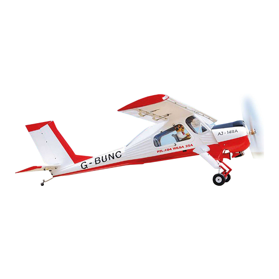
PZL - 104 - WILGA
Gas and EP
ALL BALSA - PLY WOOD CONSTRUCTION.
COVERED WITH ORACOVER.
95% ALMOST READY TO FLY
SPECIFICATION:
- Wingspan: 2,240 mm (88.19 in).
- Length: 1,625 mm (63,98 in).
- Weight: 6.4 kg (14.08 lbs).
- Wing area: 62.9 dm2.
- Wing loading: 98.6g/dm2.
- Wing type: Naca Airfoil.
- Servo mount: 42mm x 21mm.
- Gear type: Aluminium Hi-grade and oleo
struts for main gear, Aluminium Hi-grade
for tail gear (included).
Instruction Manual Book
Item code: BH124
Parts listing required (not included):
- Radio: 06 channels.
- Servo: 08 standard high torque servos.
- Engine: 25 - 35 cc gas. NGH GT25/GF30 reccomended
- Motor: Brushless outrunner 1500 - 2000W, 250KV.
- Propeller: Suit with your engine.
Recommended Motor and Battery set up
(not included):
- Motor: Admiral GP20 6320-295kV
- Lipo cell: 8 cells 4,000-5,500mAh.
- Receiver battery: 6V/ 1200mAh.
- ESC: 80 - 120A
Made in Vietnam.
Advertisement
Table of Contents

Related Manuals for Black Horse Model PZL-104-WILGA


Summary of Contents for Black Horse Model PZL-104-WILGA
- Page 1 Instruction Manual Book Item code: BH124 PZL - 104 - WILGA Gas and EP ALL BALSA - PLY WOOD CONSTRUCTION. COVERED WITH ORACOVER. 95% ALMOST READY TO FLY SPECIFICATION: - Wingspan: 2,240 mm (88.19 in). Parts listing required (not included): - Length: 1,625 mm (63,98 in).
-
Page 2: Table Of Contents
Thank you for purchasing Black Horse Model products. With over 18 years experience in production and fly testing, Black Horse Model is committed to bring the best quality products and good service to customers. Along with a team of creative engineers and skilled workers, we will always accompany with customers by our great experiences, fully enthusiasm... -
Page 3: Warranty
In that Black Horse Model has no control over the final assembly or material used for final assembly, SUGGESTION Black Horse Model is not responsible for loss of use , or other incidental or consequential damages. To avoid scratching your new airplane, do not... -
Page 4: Covering Tools
PZL-140 WILGA Item code: BH124 Instruction Manual FLIGHT WARNINGS ADHESIVES AND REQUIRED TOOLS When ready to fly, first extend the transmitter aerial. Thin CA Switch on the transmitter. 30-minute epoxy Switch on the receiver. 6-minute epoxy Check that the wings are correctly fitted to the Threadlocker thread locking cement fuselage. - Page 5 PZL-140 WILGA Item code: BH124 Instruction Manual • Officially designated AMA Air Show Teams (AST) are authorized to use devices and practices as defined within the Team AMA Program Document. (AMA Document #718.) (j) Not operate a turbine-powered aircraft, unless in compliance with the AMA turbine regulations. (AMA Document #510-A.) 3.
-
Page 6: Parts Listing (Not Included)
PZL-140 WILGA Item code: BH124 Instruction Manual PARTS LISTING (NOT INCLUDED). Servo extension leads....2 pcs. Engine: 25-35cc Gas. 420mm ..2 pcs. NGH GT35/GF38 330mm ..4 pcs. recommended 190mm ..2 pcs. Propeller. Suit with your engine. LiPo: 8S set-up = 2 x 4S 4000-5000mAh 2 Packs MOTOR... - Page 7 PZL-140 WILGA Item code: BH124 Instruction Manual : Fuselage. : Wing panel ( 2a, 2b ). : Cockpit fuselage ( 3a: Chairs, 3b: Pilot doll, 3c , 3c : Cockpit, 3d: Front Windscreen, 3e : Right window, 3e Left window, 3f: Top windscreen, 3g : Right main door, 3g : Left main door).
-
Page 8: Preparations
PZL-140 WILGA Item code: BH124 Instruction Manual PREPARATIONS Use a covering iron with a covering sock on high heat to tighten the covering if necessary. Apply pressure over sheeted areas to thoroughly bond the covering to the wood. INSTALLING THE AILERONS AND FLAPS SERVOS Place the servo into the servo tray/ hatch into the servo box on the bottom of the wing and drill 1.5mm Install the rubber grommets and brass eyelets... - Page 9 PZL-140 WILGA Item code: BH124 Instruction Manual Ball link 2x10mm Tp Screw 3mm Flat Screw 2.6x70mm Push rod - - - - 8 - - - - 4 - - - - 4 - - - - 16 Horn 3mm Hex Nut 3x12mm Tp Screw 3x12mm Cap Screw - - - - 4...
- Page 10 PZL-140 WILGA Item code: BH124 Instruction Manual Set all scerws securely. If they come 2x10mm Tp Screw Warning! off during flight you will lose control - - - - 16 of your aircraft! Assemble left and right sides the same way.
- Page 11 PZL-140 WILGA Item code: BH124 Instruction Manual 3x12mm For Aileron. For Aileron. Tp Screw For Flap. For Flap. Horn Ball Link For Aileron. For Aileron. For Flap. For Flap. 3x12mm Cap Screw...
-
Page 12: Installation The Main Gear
PZL-140 WILGA Item code: BH124 Instruction Manual INSTALLING THE MAIN GEAR 3x8mm Button Head Cap Screw 4x15mm Socket Head Cap Screw 100mm Wheels - - - - - - - - - - 2 - - - - - - - - - - - - - 6 3x10mm Button Head Cap Screw 4mm Flat Washer - - - - - - - - - - 4... - Page 13 PZL-140 WILGA Item code: BH124 Instruction Manual BOTTOM VIEW...
- Page 14 PZL-140 WILGA Item code: BH124 Instruction Manual 4x15mm Socket Head Cap Screw 4mm Spring Washer 4mm Flat Washer BOTTOM VIEW BOTTOM VIEW Apply threadlocker (screw cement). Apply instant glue (C.A glue, super glue).
- Page 15 PZL-140 WILGA Item code: BH124 Instruction Manual 3x8mm Button Head Cap Screw 3mm Hex Nut 3x10mm Button Head Cap Screw BOTTOM VIEW Apply threadlocker (screw cement).
- Page 16 PZL-140 WILGA Item code: BH124 Instruction Manual BOTTOM VIEW BOTTOM VIEW 3mm Hex Nut 3mm Hex Nut 10x14mm 10x14mm Aluminium Aluminium 3x25mm Socket 3x25mm Socket Head Cap Screw Head Cap Screw 3x10mm Button Head Cap Screw...
- Page 17 PZL-140 WILGA Item code: BH124 Instruction Manual BOTTOM VIEW 10x7mm Aluminium 10x7mm Aluminium 5mm Hex Nut 5mm Flat Washer BOTTOM VIEW 5x50mm Socket Head Cap Screw 5mm Flat Washer 5x50mm Socket Head Cap Screw Apply threadlocker (screw cement).
- Page 18 PZL-140 WILGA Item code: BH124 Instruction Manual BOTTOM VIEW 10mm Mark Line 30mm Cut off shaded portion carefully. Assemble left and right sides the same way.
- Page 19 PZL-140 WILGA Item code: BH124 Instruction Manual Push Mark Point 1 Mark Point 1 Assemble left and right sides the same way.
- Page 20 PZL-140 WILGA Item code: BH124 Instruction Manual 3x6mm Button Head Cap Screw 3x6mm Button Head Cap Screw 3x6mm Button Head Cap Screw 3x6mm Button Head Cap Screw Drill holes using the stated. (in this case 3mm Assemble left and right sides the same way.
-
Page 21: Installing The Fuselage Servos
PZL-140 WILGA Item code: BH124 Instruction Manual INSTALLING THE FUSELAGE SERVOS 1) Install the rubber grommets and brass collets into the elevator, rudder and throottle servor. Test fit the servos into the servo tray. Trim the tray if necessary to fit your servos. 2) Mount the servo to the tray using the mounting screws provided with your radio system. -
Page 22: Wing Attachment
PZL-140 WILGA Item code: BH124 Instruction Manual WING ATTACHMENT Locate the aluminium wing dihedral brace. Attach the aluminium tube into the fuselage. 25mm Aluminium tube. 798mm *** Test fit the aluminium tube dihedral brace into each wing haft. The brace should slide in easily. If not, use 220 grit sand around the edges and ends of the brace until it fits properly. - Page 23 PZL-140 WILGA Item code: BH124 Instruction Manual 4x15mm Top view Cap screw for main wing fixture...
-
Page 24: Horizontal Stabilizer Installation
PZL-140 WILGA Item code: BH124 Instruction Manual HORIZONTAL STABILIZER INSTALLATION Pinned Hinge - - - - 6 Make certain the hinges are adequately secured with glue. If they come loose in flight accidents may result. BOTTOM VIEW TOP VIEW Cut off shaded portion Apply epoxy glue. -
Page 25: Elevator Control Horn And Elevator Pushrod Installation
PZL-140 WILGA Item code: BH124 Instruction Manual 4x25mm Socket Head Cap Screw - - - - - - - - - - - - - 2 4mm Flat Washer - - - - - - - - - - - - - 2 4mm Spring Washer 4x25mm Socket Head - - - - - - - - - - - - - 2... -
Page 26: Horizontal Stabilizer Struts
PZL-140 WILGA Item code: BH124 Instruction Manual HORIZONTAL STABILIZER STRUTS 3x10mm Button Head Cap Screw Ball Link - - - - - - - - - - - - - 4 - - - - - - - - - - - - - 4 3mm Flat Washer Aluminium - - - - - - - - - - 1... - Page 27 PZL-140 WILGA Item code: BH124 Instruction Manual BOTTOM VIEW 3mm Hex Nut 3mm Flat Washer 3x10mm Button Head Cap Screw BOTTOM VIEW Apply threadlocker (screw cement).
-
Page 28: Installing Vertical Stabilizer
PZL-140 WILGA Item code: BH124 Instruction Manual 3x12mm Screw Servo arm Elevator Servo 3mm Flat washer Ball link Push rod Elevator Pushrod 3mm Hex Nut TOP VIEW Elevator Servo Elevator Pushrod Elevator INSTALLING VERTICAL STABILIZER Ball link 3x12mm Cap Screw - - - - 2 - - - - 2 3mm Hex Nut... - Page 29 PZL-140 WILGA Item code: BH124 Instruction Manual Pinned Hinge - - - - 4 TOP VIEW TOP VIEW Cut off shaded portion carefully. Apply epoxy glue.
- Page 30 PZL-140 WILGA Item code: BH124 Instruction Manual Horn 1.5mm 3x12mm Tp Screw TOP VIEW 3x12mm Cap Screw Ball link TOP VIEW Drill holes using the stated. (in this case 1.5mm 1.5mm...
- Page 31 PZL-140 WILGA Item code: BH124 Instruction Manual Plastic parts for vertical TOP VIEW TOP VIEW Apply instant glue (C.A glue, super glue).
-
Page 32: Installing The Tail Gear
PZL-140 WILGA Item code: BH124 Instruction Manual TOP VIEW 3x12mm Screw Servo arm 3mm Flat washer Ball link Push rod 3mm Hex Nut Rudder Pushrod Rudder Servo Rudder Rudder Pushrod Rudder Servo INSTALLING THE TAIL GEAR 3x15mm Button Head Cap Screw Cab link - - - - - - - - - - - - - - - - 2 - - - - - - - 2... - Page 33 PZL-140 WILGA Item code: BH124 Instruction Manual 3x15mm Button Head Cap Screw 3mm Spring Washer 3mm Flat Washer BOTTOM VIEW BOTTOM VIEW Cable Apply threadlocker (screw cement). Cut off shaded portion carefully. Must be purchased separately! Cut off excess. Crimp Drill holes using the stated.
- Page 34 PZL-140 WILGA Item code: BH124 Instruction Manual Servo tail gear TOP VIEW Servo Gear Cable Servo Gear Tail Gear Cable Pay close attention here.
-
Page 35: Installing The Engine
PZL-140 WILGA Item code: BH124 Instruction Manual INSTALLING THE ENGINE May be you also need to trim some wood from the tri-angle Using plate of plywood (supplied with the kit) mark the holes wood for the installation is easy. onto the fire wall for installing the engine mount for DLE-35CC or OS-33CC. - Page 36 PZL-140 WILGA Item code: BH124 Instruction Manual 12x60mm Aluminium 5mm Flat Washer 16x5mm Flat Washer Connector M5 Blind Nut - - - - - - - 4 - - - - - - - 4 - - - - - - - 4 - - - - - - - - 1 - - - - - - - - 4 5x90mm Socket Head...
-
Page 37: Installing The Stopper
PZL-140 WILGA Item code: BH124 Instruction Manual INSTALLING THE STOPPER Cut off shaded portion... -
Page 38: Installing The Fuel Tank
PZL-140 WILGA Item code: BH124 Instruction Manual INSTALLING THE FUEL TANK 5. When satisfied with the alignment of the stopper assembly tighten the 3mm x 20mm machine screw until the rubber stopper expands and 1. Using a modeling knife, cut one length of silicon seals the tank opening. -
Page 39: Installation The Throttle
PZL-140 WILGA Item code: BH124 Instruction Manual INSTALLING THE THROTTLE 1) Install one adjustable metal connector through the Slide the adjustable metal connector / servo arm third hole out from the center of one servo arm, assembly over the plain end of the pushrod wire. enlarge the hole in the servo arm using a 2mm drill bit Position the throttle stick and the throttle trim at their to accommodate the servo connector. -
Page 40: Mounting The Cowling
PZL-140 WILGA Item code: BH124 Instruction Manual Throttle servo MOUNTING THE COWLING Cut off shaded portion carefully. Cowl area cutout for muffler... - Page 41 PZL-140 WILGA Item code: BH124 Instruction Manual TOP VIEW 3x12mm Tp Screw - - - - - - 4 TOP VIEW C . A 3x12mm Tp Screw Apply instant glue (C.A glue, super glue). Drill holes using the stated. (in this case 2.5mm 2.5mm...
-
Page 42: Installing The Switch, Receiver And Battery
PZL-140 WILGA Item code: BH124 Instruction Manual C . A 3x12mm Tp Screw Apply instant glue (C.A glue, super glue). Drill holes using the stated. (in this case 2.5mm 2.5mm INSTALLING THE SWITCH, RECEIVER AND BATTERY INSTALLING THE SWITCH Plug the servo leads and the switch lead into the receiver. -
Page 43: Installing The Electric Motor (Ep Version)
PZL-140 WILGA Item code: BH124 Instruction Manual TOP VIEW Switch Battery Receiver Tape Foam Pad Switch Must be purchased separately! INSTALLING THE ELECTRIC MOTOR (EP VERSION) 10x20mm Aluminium 4x40mm Socket Head Cap Screw - - - - - 4 - - 4 M4 Blind Nut 4mm Flat Washer - - - - - 4... - Page 44 PZL-140 WILGA Item code: BH124 Instruction Manual 10x20mm Aluminium 4mm Spring Washer 4mm Flat Washer 4x40mm Socket Head Cap Screw TOP VIEW 16x5mm Rubber Washer 16x5mm Flat Washer 12x60mm Aluminium 5mm Spring Washer 5mm Flat Washer 5x90mm Socket Head Cap Screw Apply threadlocker Must be purchased (screw cement).
- Page 45 PZL-140 WILGA Item code: BH124 Instruction Manual Battery Cord TOP VIEW When rotating clock wise, change the connection of 2 wires. TOP VIEW Must be purchased separately!
-
Page 46: Installing The Cockpit
PZL-140 WILGA Item code: BH124 Instruction Manual INSTALLING THE COCKPIT Chairs Cockpit Pilot doll TOP VIEW Cockpit... - Page 47 PZL-140 WILGA Item code: BH124 Instruction Manual 3x16mm Button Head Cap Screw - - - - - - - - - - - - - - - 2 TOP VIEW Cockpit TOP VIEW Assemble left and right sides the same way. Drill holes using the stated.
- Page 48 PZL-140 WILGA Item code: BH124 Instruction Manual TOP VIEW Chairs TOP VIEW Assemble left and right Drill holes using the stated. sides the same way. (in this case 3mm...
- Page 49 PZL-140 WILGA Item code: BH124 Instruction Manual TOP VIEW Assemble left and right sides the same way. Apply epoxy glue. The number of times the same way Assembly (in this case twice).
-
Page 50: Installing Canopy Fuselage
PZL-140 WILGA Item code: BH124 Instruction Manual INSTALLING CANOPY FUSELAGE Position the canopy so the rear frame on the canopy is aligned with the rear edge of the cockpit opening. Use canopy glue to secure the canopy to the canopy hatch. Use low-tack tape to hold the canopy in position until the glue fully cures. - Page 51 PZL-140 WILGA Item code: BH124 Instruction Manual TOP VIEW Adhesive tape. TOP VIEW Apply epoxy glue.
- Page 52 PZL-140 WILGA Item code: BH124 Instruction Manual TOP VIEW TOP VIEW TOP VIEW Apply epoxy glue. Assemble left and right sides the same way.
- Page 53 PZL-140 WILGA Item code: BH124 Instruction Manual TOP VIEW Close Plastic parts bottom fuselage - - - - - - - - - - - - - - - - 1 BOTTOM VIEW...
-
Page 54: Installing The Propeller
PZL-140 WILGA Item code: BH124 Instruction Manual Apply instant glue (C.A glue, super glue). BOTTOM VIEW INSTALLING THE PROPELLER TOP VIEW Must be purchased separately! - Page 55 PZL-140 WILGA Item code: BH124 Instruction Manual TOP VIEW...
-
Page 56: Balancing
PZL-140 WILGA Item code: BH124 Instruction Manual BALANCING. CONTROL THROWS. 1) It is critical that your airplane be bal- 1) We highly recommend setting up a anced correctly. Improper balance will cause plane using the control throws listed. your plane to lose control and crash. -
Page 57: For Your Radio Installation Basic Connection For Airplane And Adjustment Of Servos
PZL-140 WILGA Item code: BH124 Instruction Manual FOR YOUR RADIO INSTALLATION BASIC CONNECTION FOR AIRPLANE AND ADJUSTMENT OF SERVOS Example of connection For more information, refer to radio system instruction manual. Follow instruction manual of Engine and Battery. Aileron Servo Aileron Engine Aileron Servo... -
Page 58: Main Gear Dimensional Detail
PZL-140 WILGA Item code: BH124 Instruction Manual MAIN GEAR DIMENSIONAL DETAIL 26.5mm 16mm 173mm TAIL GEAR DIMENSIONAL DETAIL 25.0 25.0... -
Page 59: Decoration
PZL-140 WILGA Item code: BH124 Instruction Manual DECORATION <Top view> <Bottom view> G- BUNC <Side view> Left G- BUNC <Side view> Right G- BUNC ORACCOVER #21 - 023 Ferri Red #21 - 071 Black #21 - 010 White... -
Page 60: Exploded View
PZL-140 WILGA Item code: BH124 Instruction Manual... - Page 61 I/C FLYING WARNINGS Always operate in open areas, away from fly near power lines,aerials or AL WAYS adjust the engine from behind NEVER factories, hospitals, schools, buildings other dangerous areas including airports, the propeller, and do not allow any part of and houses etc.
- Page 62 I/C FLYING GUIDELINES Operate the control sticks on the ALWAYS land the model INTO When ready to fly, first extend transmitter and check that the the wind, this ensures that the the transmitter aerial. control surfaces move freely and in model lands at the slowest possible the CORRECT directions.
Need help?
Do you have a question about the PZL-104-WILGA and is the answer not in the manual?
Questions and answers