Table of Contents
Advertisement
EPsolar
eTracer-BND Series
—— Maximum Power Point Tracking
Solar Charge Controller
OPERATION
MANUAL
Thank you very much for selecting our product!
This manual offers important information and suggestion about installation, use and
troubleshooting, etc. Please read this manual carefully before using the product and pay
attention to the safety recommendations in it.
Advertisement
Table of Contents

Related Manuals for Epsolar eTracer ET4415BND


Summary of Contents for Epsolar eTracer ET4415BND
- Page 1 EPsolar eTracer-BND Series —— Maximum Power Point Tracking Solar Charge Controller OPERATION MANUAL Thank you very much for selecting our product! This manual offers important information and suggestion about installation, use and troubleshooting, etc. Please read this manual carefully before using the product and pay...
- Page 3 Series —— Maximum Power Point Tracking Solar Charge Controller Models: ET4415BND/ET6415BND Final interpretation right of the manual belongs to EPsolar. Any changes without prior notice!
-
Page 4: Table Of Contents
Contents 1 Important Safety Information ..................1 2 General Information ....................2 2.1 Overview ......................2 2.2 Models & Parameters ..................3 2.3 Characteristics ....................4 2.4 Accessories ..................... 6 3 Installation Instructions ....................7 3.1 General Installation Notes ................7 3.2 Mounting ...................... -
Page 5: Important Safety Information
1 Important Safety Information This manual contains important safety, installation and operating instructions for the eTracer-BND Series MPPT solar controller. Save these instructions. The following symbols are used throughout this manual to indicate potentially dangerous conditions or mark important safety instructions. WARNING: Indicates a potentially dangerous condition. -
Page 6: General Information
2 General Information 2.1 Overview Thank you for selecting the eTracer-BND Series MPPT solar controller. The controller is a high-end industrial class product based on multiphase synchronous rectification technology and has the features of high efficiency and reliability. The features are listed below: ... -
Page 7: Models & Parameters
The battery charging process has been optimized for long battery life and improved system performance. The comprehensive self-diagnostics and electronic protection functions can prevent damage from installation mistakes or system faults. Please take the time to read this operation's manual and become familiar with the controller. -
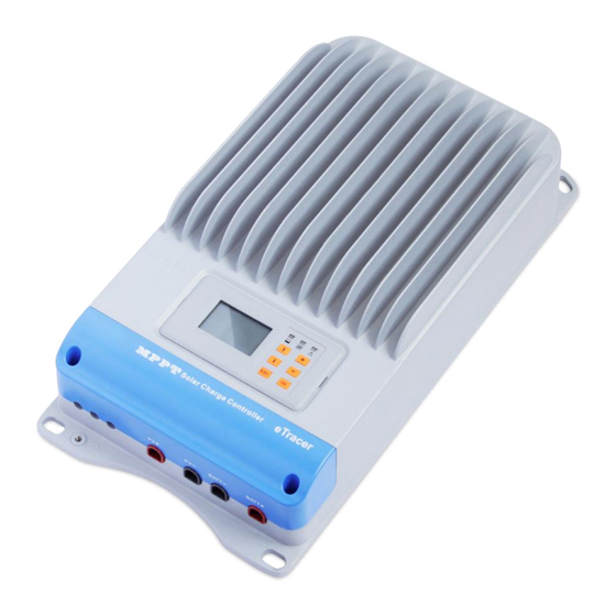
Page 8: Characteristics
2.3 Characteristics Figure 2-1 eTracer-BND features... - Page 9 1 – Heat Sink Aluminum heat sink to dissipate controller heat. 2 – LCD Display the status and data. 3 – Battery LED indicator Three states of battery LED indicator show charging status. 4 – Charging LED indicator Indicate that the battery is charging or not. 5 –...
-
Page 10: Accessories
USB To RS-485 Converter(Model:CC-USB-RS485-150U-3.81) The USB to RS-485 converter is used to monitor each controller on the network using EPsolar Station PC software and update the firmware. The length of cable is 1.5m. The CC-USB-RS485-150U-3.81 connects to the MC1.5-5.08-2L port (8 ) on the controller. -
Page 11: Installation Instructions
3 Installation Instructions 3.1 General Installation Notes Read through the entire installation section first before beginning installation. Be very careful when working with batteries. Wear eye protection. Have fresh water available to wash and clean any contact with battery acid. ... -
Page 12: Mounting
3.2 Mounting NOTE: The eTracer-BND controller requires at least 150mm of clearance above and below for proper air flow. Ventilation is highly recommended if mounted in an enclosure. WARNING: Risk of explosion! Never install the eTracer-BND in a sealed enclose with flooded batteries! Do not install in a confined area where battery gas can accumulate. -
Page 13: Wiring
Step3: Mark Holes Mark the four (4) mounting holes locations on the mounting surface. Step 4: Drill Holes Remove the controller and drill four sizeable holes at the marked locations. Step 5: Secure the Controller Place the controller on the surface and align the mounting holes with the drilled holes in step 4. - Page 14 can be connected to either screw terminal. No damage will result if connect the RTS300R10K5.08A to the remote battery voltage sense port, but the connection will not be recognized. Step 2: Remote Battery Voltage Sensor Connection NOTE: When connecting Remote Battery Voltage Sensor, please pay attention to ‗+‘...
- Page 15 There are two kinds of communication: RS-232 and RS-485. Please use matching communication cables and make sure the cables are connected firmly during data transmitting: the below features are supported with communication interface: Monitor each controller on the network using EPsolar Station PC software; update the firmware; · RS-232,RS-485 Connection The series port on eTracer-BND controller is a standard 3.81-4P port.
- Page 16 Connecting a breaker in series in the solar circuit is recommended, and the breaker must be 1.25 to 2 times of the rated current. Keep OFF before connection. Connect solar positive (+) and negative (-) to solar terminals on the controller in the figure 2-1. Please pay much attention to ‗+‘...
-
Page 17: Operation
4 Operation 4.1 MPPT Technology The eTracer-BND utilizes Maximum Power Point Tracking technology to extract maximum power from the solar array. The tracking algorithm is fully automatic and does not require user adjustment. eTracer-BND technology will track the array maximum power point voltage (V ) as it varies with weather conditions, ensuring that maximum power is harvested from the array through the course of the day. - Page 18 . In a 12V system for example, the battery voltage may range from 11 to 15Vdc but the module‘s V is typically around 16 or 17V. Figure 4-1 shows a typical current VS. Voltage output curve for a nominal 12V off-grid module.
-
Page 19: Battery Charging Information
an array V greater than battery voltage. Additionally, the savings in wiring due to reduced solar current make MPPT worthwhile even in hot climates. 4.2 Battery Charging Information The eTracer-BND has a 4 stages battery charging algorithm for rapid, efficient, and safe battery charging. - Page 20 and current. It will reduce the temperature of battery and prevent the gassing and charge the battery slightly at the same time. The purpose of Float stage is to offset the power consumption caused by self consumption, while maintaining full battery storage capacity.
-
Page 21: Led Indication
4.3 LED Indication Charging LED Indicator Status Green Blink Charging Green OFF No charging Battery LED Indicator Status Green ON Normal Green slow blink Full Orange ON Under voltage warning Red ON Low voltage disconnect Red Blink Battery over temperature Green fast blink High volt disconnect Fault LED... -
Page 22: Lcd Display & Operation
4.4 LCD Display & Operation Initialization LCD will paint the picture as shown on the left as soon Efficient Power as it is powered on. It indicates that initialization is normal when the interface goes automatically to the Rated Info interface. ... - Page 23 Monitor There are 9 interfaces for monitoring, as shown below: Batt. Temp Local Temp 21º C 24.0 º C Temp Coefficient -3mV/º C/2V Batt.Volt Total Generated 12.4V 7.50kWh Batt. Curr 2.2A Batt. Day‘Max Generated Energy 13.5V 1.5kWh/D Batt. Day‘ Min PV Power 11.7V 85.5W...
- Page 24 Alarm Log Query 1/10 <1>Work Log From 2012-01-01 Batt OVD/Begin <2>Alarm Log 2012-06-08 2012-01-04 14:20 Total:10 Para 17.20V Press OK to enter the monitoring interface when the inverse cursor point to monitor item. Press ESC button to exit. Work Log and Event Log could be browsed in this interface, the operation is as follows: Press OK to enter the Work Log or Event Log interface respectively when the item is chosen in inverse.
- Page 25 NOTE:The log after the current time will be erased when the clock has be adjusted. Device Parameter There are 3 interfaces about device parameter as shown blew: Local ID Backlight Time T03-0001 60 s Storage Interval 10min Press OK to enter the Device Parameter interface when the inverse cursor point to Device Para item.
- Page 26 Temp Coefficient Over Volt. Rect Batt Type Over Volt. Disc. 31.0V SEALED 32.0V -3mV/℃/2V Equalize Charge Batt AH Charge Limit Rated Volt 29.2V 200AH 30.0V AUTO Batt. Manag. Boost Charge Char.SOC: 100% 28.8V Disc.SOC: 30% Float Charge Vol.Com. SOC 27.6V Under Volt Rect Boost Rect Volt Low Volt Disc...
- Page 27 Others Parameter Default value Range Battery capacity 200Ah 1~9999Ah Temperature compensate -3mV/º C/2V -9~0 mV/º C/2V coefficient Rated system voltage Auto 12/24/36/48VDC Auto Percent of charging 100% 100% constant value(SOC charging mode) Percent of discharging 10~80% (SOC charging mode) Battery Control Parameters All the coefficient is referred to 25℃, and twice in 24V system rate, triple in 36Vsystem rate and quadruple in 48Vsystem rate.
- Page 28 Password Press OK to enter the Password Set interface when the inverse cursor points to Password Para item. Press ESC button to exit. Note: The factory default password is “ 000000”. Sys Password Old PSW 000000 New PSW 000000 ...
-
Page 29: Protections, Troubleshooting & Maintenance
5 Protections, Troubleshooting & Maintenance 5.1 Protections ·PV Short Circuit When PV short circuit occurs, the controller will stop charging. Clear it to resume normal operation. ·PV Over Voltage If PV voltage is larger than maximum input open voltage 150V, PV will remain disconnected and warning until the voltage falls safely below 145V. -
Page 30: Maintenance
Fault LED indicator blink, LCD displaying ‗Current Err‘ Probable Cause: Charging current in three phases is unbalanced. Solution: Disconnect solar modules and restart the eTracer-BND; if the fault still exists, please contact the supplier to make maintenance. Fault LED indicator blink, LCD displaying ‗Over Volt‘ Probable Cause: solar modular output is too high. - Page 31 Check and confirm that LED or LCD is consistent with required. Pay attention to any troubleshooting or error indication .Take necessary corrective action. Confirm that all the system components are ground connected tightly and correctly. Confirm that all the terminals have no corrosion, insulation damaged, high temperature or burnt/discolored sign, tighten terminal screws to the suggested torque.
-
Page 32: Pc Software
6 PC Software The eTracer-BND controller can be connected to a common PC monitoring software by supporting USB communication cable developed by the EPsolar company. Monitoring software can remote single or more controllers to modify the parameters and others in the PV system management (username: administrator, password: 111111 as default). - Page 33 Figure6-2 Real Time Monitoring Figure6-3 Control Parameter...
-
Page 34: Warranty
This information is critical to a rapid disposition of your warranty claim. If the products failure is caused by customers‘ misuse or not following the manual, EPsolar won‘t be responsible for the free maintenance. We will ask for the raw material cost. And please refer to above procedure. -
Page 35: Specifications
8 Specifications Electrical Parameters ET4415BND ET6415BND Nominal System Voltage 12/24/36/48VDC Auto Nominal Battery Current Maximum Solar Input Voltage 150V Battery Voltage Range 8~72V Maximum Input Power 12V: 600W 800W 24V: 1200W 1600W 36V: 1800W 2400W 48V: 2400 W 3200W Self Consumption 1.4~2.2W Grounding Common Negative Grounding... - Page 36 Protection Solar input short protection Solar input reversed polarity protection Solar input reverse current protect at night Battery reversed polarity protection Battery over voltage disconnect protection Battery over voltage reconnect protection Battery over temperature disconnect protection Controller over temperature disconnect protection Abbreviation High voltage disconnect Low voltage disconnect...
-
Page 37: Conversion Efficiency Curves
9 Conversion Efficiency Curves Illumination Intensity: 1000W/m Temperature: 25℃ Test model: ET4415BND Solar MPPT Voltage(66V, 98V, 115V) / System Voltage(12V) Solar MPPT Voltage(33V, 66V, 98V, 115V) / System Voltage(24V) - Page 38 Solar MPPT Voltage(66V, 98V, 115V) / System Voltage(36V) Solar MPPT Voltage(66V, 98V, 115V) / System Voltage(48V)
- Page 39 Test model: ET6415BND Solar MPPT Voltage(17V,34V,68V) / System Voltage(12V) Solar MPPT Voltage(34V,68V,115V) / System Voltage(24V)
- Page 40 Solar MPPT Voltage(68V,115V) / System Voltage(36V) Solar MPPT Voltage(68V,115V) / System Voltage(48V)
-
Page 41: Dimensions
10 Dimensions ET4415BND Dimensions(Unit:mm)... - Page 42 ET6415BND Dimensions(Unit:mm) Version:V1.4...
- Page 44 BEIJING EPSOLAR TECHNOLOGY CO., LTD. Tel: +86-10-82894112 / 82894962 Fax: +86-10-82894882 E-mail:info@epsolarpv.com Website: http://www.epsolarpv.com/...
Need help?
Do you have a question about the eTracer ET4415BND and is the answer not in the manual?
Questions and answers