Table of Contents
Advertisement
Utility model patent NO.
EPSOLAR
201120064092.1
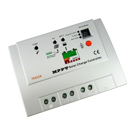
Tracer-1206RN / 1210RN / 1215RN
—— Maximum Power Point Tracking Solar Charge Controller
INSTRUCTION
MANUAL
Thank you very much for selecting our product!
This manual offers important information and suggestions with respect to
installation, use and troubleshooting, etc. Please read this manual carefully
before using the product and pay attention to the safety recommendations
in it.
Advertisement
Table of Contents
Troubleshooting


Need help?
Do you have a question about the Tracer-1206RN and is the answer not in the manual?
Questions and answers
What is the Maximum open Cicute voltage of 1210