Advertisement
Advertisement
Table of Contents
Troubleshooting

Related Manuals for Epsolar LandStar LS-EU Series


Summary of Contents for Epsolar LandStar LS-EU Series
- Page 1 LS-EU Series Solar Charge Controller —— USER MANUAL...
- Page 3 LandStar LS-EU Series Solar Charge Controller —— LS0512EU/LS1012EU 12VDC Nominal System Voltage LS1024EU/LS2024EU 12/24VDC LS0512EU/LS1012EU Maximum PV Input Voltage LS1024EU/LS2024EU LS0512EU Nominal LS1012EU/LS1024EU Charge/Discharge Current LS2024EU USB Output 5VDC/1.2A...
-
Page 4: Table Of Contents
Contents 1 Important Safety Information.......... 1 2 General Information............2 3 Installation Instructions........... 3 3.1 Mounting ..............3 3.2 Wiring ..............4 4 Operation................. 5 4.1 LED Indicators ............5 4.2 Setting Operation ............ 7 5 Protection and Troubleshooting........8 5.1 Protection ..............8 5.2 Troubleshooting ............ -
Page 5: Important Safety Information
1 Important Safety Information Read all of the instructions and cautions in the manual before beginning installation. There are no user serviceable parts inside the controller. Do not disassemble or attempt to repair it. Install external fuses/breakers as required. ... -
Page 6: General Information
2 General Information LS-EU series solar charge controller, with beautiful, economic, practical, simple and easy to use, etc. It has various unique functions : It can be judged battery voltage intuitively with Battery indicator. High efficient Series PWM charging, increase the battery lifetime and improve the solar system performance. -
Page 7: Installation Instructions
3 Installation Instructions 3.1 Mounting Read through the entire installation section first before beginning installation. Be very careful when working with batteries. Wear eye protection. Have fresh water available to wash and clean any contact with battery acid. Uses insulated tools and avoid placing metal objects near the batteries. -
Page 8: Wiring
Wiring 1. Connect components to the charge controller in the sequence as shown in above picture and pay much attention to the “+” and “-”.Always power the battery First. 2. After power the battery, check the battery indicator on the controller, it will be green. -
Page 9: Operation
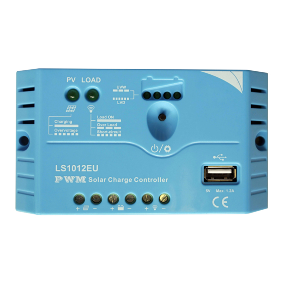
4 Operation 4.1 LED Indicators LED2 Load status indicator LED4 Charging status indicator LED1 LED3 Setting button Mounting Holes Load Solar Module Battery Terminals Terminals Terminals Charging and load status indicator Table 4-1 Indicator System Indicator Note Status Status Charging Normal Charging... - Page 10 rated current for 5 seconds Fast Short refer to section 5 Flashing Circuit Battery status indicator(LED1、LED2、LED3、LED4) Battery LED indicator(The parameters in the table below is for 12VDC system at 25℃, for 24VDC system ,the parameters is doubled) Table 4-2 LED1 LED2 LED3 LED4...
-
Page 11: Setting Operation
4.2 Setting Operation Load Work Mode Setting When the controller is powered on, press the setting button to control the load output. Press the button once, the ON/OFF status will be changed corresponding. The USB Output is ON only when the Load Work Mode is at ON status, otherwise, it is OFF. -
Page 12: Protection And Troubleshooting
5 Protection and Troubleshooting 5.1 Protection ·Load Overload If the load current exceeds the maximum load current rating(exceeds 1.25 times of rated current), the controller will disconnect the load with a short delay. Overloading must be cleared up through reapply power or pressing the setting button. -
Page 13: Troubleshooting
·High Voltage Transients PV is protected against high voltage transients. In lightning prone areas, additional external suppression is recommended. 5.2 Troubleshooting Trouble Shooting Table 5-1 Possible Faults Troubleshooting reasons Charging LED Check that PV and indicator off array battery wire connections are during daytime disconnection correct and tight. - Page 14 Battery LED1 Battery When the controller cut off indicator over the output automatically, FAST discharged LED status will return to ON FLASHING. automatically when fully charged. Load Over load Please reduce the load and indicator press the button once, the SLOWLY controller will resume to FLASHING...
-
Page 15: Technical Specifications
6 Technical specifications Electrical Parameters Table 7-1 Description Type Parameter LS0512EU/LS1012EU 12VDC Nominal System Voltage LS1024EU/LS2024EU 12/24VDC LS0512EU/LS1012EU Max.batt.Volt.to the controller LS1024EU/LS2024EU LS0512EU Rated Battery Current LS1012EU/LS1024EU LS2024EU Charge Circuit Voltage ≤0.26V Drop Discharge Circuit Voltage ≤0.15V Drop Self-consumption ≤6mA Temperature Compensation Coefficient Table7-2 Description... - Page 16 Enclosure IP30 Mechanical Parameters Table 7-4 Type LS0512EU LS1012EU Overall 109.7(4.32)x65.5(2.58)x 120.3(4.74)x67(2.64)x Dimension 20.8(0.82)mm(inches) 21.8(0.86)mm(inches) Mounting 100.9(3.97)mm(inches) 111.5(4.39)mm(inches) dimension Mounting hole size Φ4.5 Φ4.5 Terminal 2.5mm² 4mm² Weight 103g Mechanical Parameters Table 7-5 Type LS1024EU LS2024EU Overall 120.3(4.74)x67(2.64)x 148(5.83)x85.6(3.37)x Dimension 21.8(0.86)mm(inches) 34.8(1.37)mm(inches) Mounting dimension...
- Page 18 Final interpretation right of the manual belongs to our company. Any changes without prior notice! Version number: V1.3...
Need help?
Do you have a question about the LandStar LS-EU Series and is the answer not in the manual?
Questions and answers