Table of Contents
Advertisement
Advertisement
Table of Contents
Troubleshooting

Related Manuals for Epsolar Tracer1215BN


Summary of Contents for Epsolar Tracer1215BN
- Page 1 Tracer- BN Series MPPT Solar Charge Controller —— User Manual...
- Page 2 Important Safety Instructions Please reserve this manual for future review. This manual contains all instructions of safety, installation and operation for Maximum Power Point Tracking (MPPT) controller in Tracer-BN series ("the controller" is referred in this manual). General Safety Information ...
-
Page 3: Table Of Contents
Contents 1 General Information ................1 1.1 Overview ..................1 1.2 Characteristics ................2 1.3 Accessories Instructions ............3 1.4 Maximum Power Point Tracking Technology ......3 1.5 Battery Charging Stage ............. 5 2 Installation Instructions ................ 8 2.1 General Installation Notes ............8 2.2 PV Array Requirements ............ -
Page 4: General Information
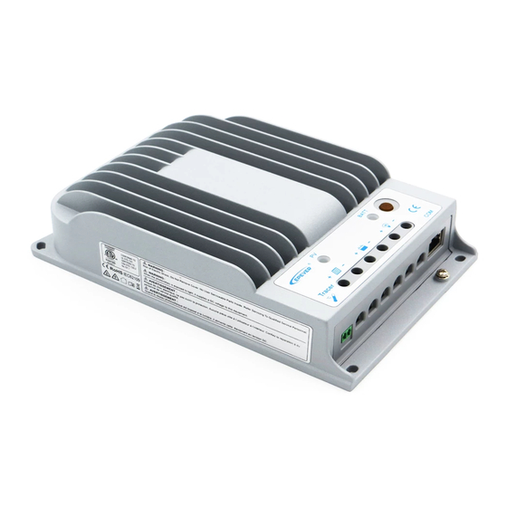
1 General Information 1.1 Overview Appreciate you for choosing MPPT solar charge controller, Tracer-BN series. Based on common negative design and advanced MPPT control algorithm, with die-cast aluminum design for heat dissipation, products in this series are artistic, economical and practical. With MPPT control algorithm, in any situation, products of this series can fast and accurately track out the best maximum power point (MPP) of photovoltaic array, in order to obtain the maximum solar energy in time, which remarkably improves... -
Page 5: Characteristics
situations. Available for PC monitoring and external display unit connecting like MT50 and so on, realizing real-time data checking and parameters setting. Support software upgrade. 1.2 Characteristics ① ⑨ ② ③ ⑧ ⑦ ④ ⑤ ⑥ Figure 1-1 Tracer-BN Series Characteristics Item Name Item... -
Page 6: Accessories Instructions
② Monitor controller by PC and update controller software via RS485 (RJ45 interface). 1.3 Accessories Instructions 1. Remote Temperature Sensor (Model: RTS300R47K3.81A) Acquisition of battery temperature for undertaking temperature compensation of control parameters, the standard length of the cable is 3m (length can be customized). - Page 7 Input power (P )= Output power (P Input voltage (V ) *input current (I ) =Battery voltage (V ) *battery current (I Normally, the V is always higher than V , Due to the principle of conservation of energy, the I is always higher than I .
-
Page 8: Battery Charging Stage
Figure 1-3 Mutil-MPP Curve If the program works improperly after appearing Multi-MPP, the system will not work on the real max power point, which may waste most solar energy resources and seriously affect the normal operation of the system. The typical MPPT algorithm, designed by our company, can track the real MPP quickly and accurately, improve the utilization rate of the array and avoid the waste of resources. - Page 9 A) Bulk Charging In this stage, the battery voltage has not yet reached constant voltage (Equalize or Boost Voltage), the controller operates in constant current mode, delivering its maximum current to the batteries (MPPT Charging). B) Constant Charging When the battery voltage reaches the constant voltage setpoint, the controller will start to operate in constant charging mode, this process is no longer MPPT charging, and in the meantime the charging current will drop gradually, the process is not the MPPT charging.
- Page 10 ATTENTION: Dégât sur l'équipement! L'égalisation peut augmenter la tension de la batterie jusqu'à un niveau nuisible pour les charges CC sensibles. Vérifiez que la tension d'entrée autorisées de toutes les charges disponibles sont supérieures à 11% à la tension du point d'installation de chargement d'égalisation.
-
Page 11: Installation Instructions
2 Installation Instructions 2.1 General Installation Notes Before installation, please read through the entire installation instructions to get familiar with the installation steps. Be very careful when installing the batteries, especially flooded lead-acid battery. Please wear eye protection, and have fresh water available to wash and clean any contact with battery acid. - Page 12 PV modules can be calculated. The below table is for reference only. 36cell 48cell 54cell 60cell System Voc<23V Voc<31V Voc<34V Voc<38V voltage MAX. Best MAX. Best MAX. Best MAX. Best 72cell Voc<46V 96cell Voc<62V System Thin-Film Module voltage Voc>80V MAX. Best MAX.
-
Page 13: Wire Size
Rated Charge Rated Charge Max. PV Array Max. PV open Model Current Power Power circuit voltage 130W/12V 390W/12V Tracer1215BN 260W/24V 780W/24V 260W/12V 780W/12V ① Tracer2215BN 150V 520W/24V 1560W/24V ② 390W/12V 1170W/12V 138V Tracer3215BN 780W/24V 2340W/24V 520W/12V 1560W/12V Tracer4215BN 1040W/24V 3120W/24V ①At minimum operating environment temperature... -
Page 14: Mounting
Note: The wire size is only for reference. If there is a long distance between the PV array and the controller or between the controller and the battery, larger wires can be used to reduce the voltage drop and improve performance. 2.4 Mounting CAUTION: The controller requires at least 150mm of clearance above and below for proper air flow. - Page 15 Figure 2-1 Mounting 1) Connect components to the charge controller in the sequence as shown above and pay much attention to the ―+‖ and ―-‖. Please don‘t turn on the fuse during the installation. When disconnecting the system, the order will be reserved. 2) After installation, power the controller and check the battery indicator on the controller, it will be green.
-
Page 16: Operation
3 Operation 3.1 LED Indication LED Indication Color Indicator Status PV connection normal Green On Solid voltage(irradiance) from PV, no charging Green Slowly Flashing(1Hz) In charging No PV voltage(night Green time) or PV connection problem Green On Solid Normal Green Slowly Flashing(1Hz) Full Green... - Page 17 Four methods to configure the controller: 1–Remote meter, MT50 (Use standard twisted net cable, model: CC-RS485-RS485-200U-MT). 2–Super parameter programmer, SPP-02(Use standard twisted net cable, model: CC-RS485-RS485-200U). One-key easily configure and apply to batch setting. 3–PC monitoring setting software ―Solar Station Monitor‖(Use USB to RS485 converter cable with model: CC-USB-RS485-150U.
-
Page 18: Battery Type
3.3 Battery Type 1) Sealed (Default) 2) Gel 3) Flooded 4) User Battery Voltage Parameters (parameters is in 12V system at 25℃, please use double value in 24V.) Battery charging setting Sealed Flooded User Over Voltage Disconnect 16.0V 16.0V 16.0V 9~17V Voltage Charging Limit Voltage... -
Page 19: Load Set Mode
d. Under Voltage Warning Reconnect Voltage > Under Voltage Warning Voltage ≥ Discharging Limit Voltage. e. Boost Reconnect Charging voltage > Low Voltage Disconnect Voltage. CAUTION: Please refer to user guide or contact with the sales for the detail of setting operation. 3.4 Load Set Mode 1.Manual Control (default) The load can be switched by button or remote control command. -
Page 20: Protections, Troubleshooting And Maintenance
Protections, Troubleshooting and Maintenance 4.1 Protection PV Over Current The controller will limit battery charging current to the Maximum Battery Current rating. Therefore an over-sized solar array will not operate at peak power. PV Short Circuit When PV short circuit occurs, the controller will stop charging. Clear it to resume normal operation. -
Page 21: Troubleshooting
Damaged Remote Temperature Sensor If the temperature sensor is short-circuited or damaged, the controller will be charging or discharging at the default temperature 25℃ to prevent the battery damaged from overcharging or over discharged. Controller Overheating If the temperature of the controller heat sinks exceeds 85℃, the controller will automatically start the overheating protection and recover below 75℃. -
Page 22: Maintenance
indicators blink. voltage match with the controller (battery indicator working voltage. Please change red blink) to a suitable battery or reset the working voltage. Remove all faults and click the button to resume to work Remove or reduce the load and Load terminals Over load or Short press the button, the controller... -
Page 23: Technical Specifications
≤95% (N.C.) Humidity range Enclosure IP30 * Please operate controller at permitted ambient temperature. If over permissible range, please derate capacity in service. Mechanical Parameters Mechanical Tracer1215BN Tracer2215BN Dimension 196x117.8x36mm 216.6x142.6x56mm Mounting dimension 106mm x 185mm 130mm x 204mm Φ4.7... -
Page 24: Annex I Conversion Efficiency Curve
Annex I Conversion Efficiency Curve Illumination Intensity: 1000W/m Temp: 25º C Model: Tracer1215BN Solar Module MPP Voltage(16.5V, 34V, 66V) / Nominal System Voltage(12V) 2. Solar Module MPP Voltage(34V, 66V, 98V) / Nominal System Voltage(24V) 24V Conversion Efficiency Curves Charging Power(W) - Page 25 Model: Tracer2215BN 1.Solar Module MPP Voltage(16.5V, 33V, 66V) / Nominal System Voltage(12V) 2.Solar Module MPP Voltage(33V, 66V, 98V) / Nominal System Voltage(24V) 24V Conversion Efficiency Curves Charging Power(W)
- Page 26 Model: Tracer3215BN 1.Solar Module MPP Voltage(16.5V, 33V, 66V) / Nominal System Voltage(12V) 12V Conversion Efficiency Curves 16.5V Charging Power(W) 2.Solar Module MPP Voltage(33V, 66V, 98V) / Nominal System Voltage(24V) 24V Conversion Efficiency Curves Charging Power(W)
- Page 27 Model: Tracer4215BN 1.Solar Module MPP Voltage(16.5V, 33V, 66V) / Nominal System Voltage(12V) 2.Solar Module MPP Voltage(33V, 66V, 98V) / Nominal System Voltage(24V)
-
Page 28: Annex Ii Dimensions
Annex II Dimensions Tracer1215BN Dimensions in Millimeters... - Page 29 Tracer2215BN Dimensions in Millimeters...
- Page 30 Tracer3215BN Dimensions in Millimeters...
- Page 31 Tracer4215BN Dimensions in Millimeters Final interpretation right of the manual belongs to EPsolar. Any changes without prior notice! Version number: V1.2...
Need help?
Do you have a question about the Tracer1215BN and is the answer not in the manual?
Questions and answers