
Related Manuals for Epsolar ET2415N


Summary of Contents for Epsolar ET2415N
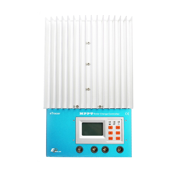
- Page 1 EPsolar eTracer series —— Network Maximum Power Point Tracking Solar Charge Controller OPERATION MANUAL Models: ET2415N ET3415N ET4415N ET6415N...
- Page 2 This manual offers important information and suggestion about installation, use and troubleshooting, etc. Please read this manual carefully before using the product and pay attention to the safety recommendations in it. Final interpretation right of the manual belongs to EPsolar. Any changes without prior notice!...
-
Page 3: Table Of Contents
Contents 1.0 Important Safety Information .............. 1 2.0 General Information ................2 2.1 Overview ....................... 2 2.2 Models & Parameters..................3 2.3 Characteristics....................4 2.4 Optional Accessories ..................6 3.0 Installation Instructions ............... 7 3.1 General Installation Notes................7 3.2 Mounting ....................... 7 3.3 Wiring ...................... -
Page 5: Important Safety Information
1.0 Important Safety Information This manual contains important safety, installation and operating instructions for eTracer. Save these instructions. The following symbols are used throughout this manual to indicate potentially dangerous conditions or mark important safety instructions. please take care when meeting these symbols. -
Page 6: General Information
2.0 General Information 2.1 Overview Thank you for selecting the eTracer controller. With the features of industrial class product of high efficiency and reliability, the controller is a high-end product based on multiphase synchronous rectification technology. The features are listed below: ·12V/24V/36V/48V auto work ·Excellent EMC design ·Thermal design and nature air cooling... -
Page 7: Models & Parameters
2.2 Models & Parameters Standard RS232, CAN BUS and ETHERNET communication interface 12V/24V/36V/48V system voltage auto work* Max. PV input voltage DC150V** Rated charging current Max. PV input power 1040W ET2415N 1600W ET3415N 2400W ET4415N 3200W ET6415N Every time start up the controller, system voltage automatically identified, do not need your any operation or setting. -
Page 8: Characteristics
2.3 Characteristics Batt. Figure 2-1 Characteristics Page... - Page 9 10 – Remote Temperature Sensor Port (MC1.5-3.81-2L) Connect RTS, Measure battery temperature to make temperature compensation. 11 – Remote Battery Voltage Sensor Port (MC1.5-3.81-2L) Connect RBVS, measure battery voltage accurately. 12 – CAN BUS Port (MC1.5-3.81-4L) Communicate with other CAN BUS devices made by EPsolar. Page...
-
Page 10: Optional Accessories
2.4 Optional Accessories Remote Temperature Sensor (Model: RTS300RA) Acquiring of battery temperature for undertaking temperature compensation of control parameters, the standard length of the cable is 2m (can be customized if want longer). The RTS300RA connects to the MC1.5-3.81-2L port (10 ) on the controller. -
Page 11: Installation Instructions
3.0 Installation Instructions 3.1 General Installation Notes ·Read through the entire installation section first before installation. ·Be very careful when working with batteries. Wear eye protection. Have fresh water available to wash and clean any contact with battery acid. ·Uses insulated tools and avoid placing metal objects near the batteries. ·Explosive battery gasses may be present during charging. - Page 12 enclosure, ventilation is highly recommended. WARNING: Risk of explosion! Never install the eTracer in a sealed enclose with flooded batteries! Do not install in a confined area where battery gas can accumulate. Step 1: Choose Mounting Location Locate the eTracer on a vertical surface protected from direct sun, high temperature, and water.
-
Page 13: Wiring
Step 3: Mark Holes Mark the four (4) mounting hole locations on the mounting surface. Step 4: Drill Holes Remove the controller and drill four sizeable holes in the marked locations. Step 5: Secure Controller Place the controller on the surface and align the mounting holes with the drilled holes in step 4. - Page 14 The included remote temperature sensor RTS300RA is recommended for effective temperature compensated charging. Connect the RTS300RA the10 port (MC1.5-3.81-2L) on the controller (see figure 2-1). There is no polarity, so either wire (+ or -) can be connected to either screw terminal. No damage will occur if connect the RTS300RA to the remote battery voltage sense port, but the connection...
- Page 15 There are three kinds of communication: RS-232, CAN BUS and Ethernet. Please use matching communication cables and make sure the cables are connected firmly during data transmits · RS-232 Connection: The serial RS-232 port is a standard 9-pin (DB9) male connector. Refer to 9 port on the controller...
- Page 16 Connecting a breaker in series in the solar circuit is recommended, and the breaker must be 1.25 to 2 times of the rated current. Make it keep OFF state before connection. Connect solar positive (+) and negative (-) to battery terminals on the controller in the figure 2-1.
-
Page 17: Operation
4.0 Operation 4.1 MPPT Technology The eTracer utilizes Maximum Power Point Tracking technology to extract maximum power from the solar module(s). The tracking algorithm is fully automatic and does not require user adjustment. eTracer technology will track the array maximum power point voltage (Vmp) as it varies with weather conditions, ensuring that maximum power is harvested from the array through the course of the day. - Page 18 the module’s Vmp. In a 12V system for example, the battery voltage may range from 11-15Vdc but the module’s Vmp is typically around 16 or 17V. Figure 4-1 shows a typical current VS. voltage output curve for a nominal 12V off-grid module.
-
Page 19: Battery Charging Information
4.2 Battery Charging Information The eTracer has a 3 stages battery charging algorithm for rapid, efficient, and safe battery charging. eTracer Figure 4-2 charging algorithm ·Bulk Charge In this stage, the battery voltage has not yet reached boost voltage and 100% of available solar power is used to recharge the battery. - Page 20 reduces the voltage to the floating stage, charging with a smaller voltage and current. It will reduce the temperature of battery and prevent the gassing, also charging the battery slightly at the same time. The purpose of Float stage is to offset the power consumption caused by self consumption and small loads in the whole system, while maintaining full battery storage capacity.
-
Page 21: Led Indication
The controller will equalize the battery on 28 each month. The constant equalization period is 60~180 minutes. If the equalization isn’t accomplished in one-time, the equalization recharge time will be accumulated until the set time is finished. Equalize charge and boost charge are not carried out constantly in a full charge process to avoid too much gas precipitation or overheating of battery. - Page 22 Initialization When the controller is powered on, the LCD displays Welcome! the information as shown in the picture. It indicates that initialization is normal when the interface goes EPsolar automatically to the monitoring interface. Main Menu Monitoring Clock Set Control Para...
- Page 23 Press button to moves inverse cursor among 8 menus. Press to enter corresponding interface. Monitoring interface There are 7 interfaces for monitoring, as shown in the picture. Click button to change interface in turn. Click button to return main menu in any monitoring interface. Batt Volt.
- Page 24 For the Abbreviation Explanations,please refer to Annex 1 The parameters in monitoring interface are only for browse. Control Para There’s 9 interfaces for ‘Control Parameters’, as shown in the Figure 4.4.3. And display 2 kinds of mode-- Browse & Setting mode. In setting mode, all the parameters can be modified.
- Page 25 Table 4.4.2: System parameter Item Default Option & Range Device ID M01- 0000~9999, use to differentiate the data 0000 belong to which device 英文 en ‘英文 en’ , ‘中文 cn’ Language 1~30 Minutes, ‘--’ means always ON Backlight Time 20 Min Storage Interval 20 Min 1~30 Minutes,...
- Page 26 MAC Add. ede025125328 Refer user’s network IP Add. 192.168.000.002 Refer user’s network Subnet Mask 255.255.255.000 Refer user’s network Default Gateway 192.168.000.001 Refer user’s network Note: In the same network, MAC address must be unique to each controller. Otherwise communication error will occur. ...
- Page 27 Notes: ‘From’ time must be ahead of ‘To’ time, or else, there will be ‘Para Error’ pop out. Browse interface includes: warning event sequence number, warning event, start or end time, parameter value. (Refer to log 2 ) For Event explanations, please refer to Annex1! ...
- Page 28 Notes: Please remember the password. The default is ‘000000’. Tip Message will popup only when input wrong. If right, there will be no tip. Default Set In this interface, user can restore default parameters. Default Set Click to enter setting mode’, use moving cursor, if select ‘Yes’, and press , all parameters will be recovered to default, and saved.
-
Page 29: Networking & Communication
5.0 Networking & communication 5.1 Introduction Note: Windows XP /windows 7 are recommended! IE7.0 or above is recommended! Can’t compatible with the safari browser of Mac OS X! CAUTION: Risk of Tampering! The eTracer doesn’t feature built-in network security. It is the responsibility of the user or network administrator to install the eTracer behind a network firewall to prevent unauthorized access. -
Page 30: Setting
Web pages Connect the eTracer controller to the network. Open a web browser on any PC on the network. Enter the IP address of the controller (‘192.168.0.2’ by default) in the address bar of the web browser. The login webpage will load. - Page 31 Real Time Data Click ‘Real Time Data’ on the left side to view real-time operating parameters. Page...
- Page 32 Ctr Para Set Click ‘Ctl Para Set’ on the left side to enter Control Parameter Set page and the system will display the current control parameter configuration. Users can also modify control parameters. After users modify control parameters and click ‘Submit’, if it is successfully adjusted, ‘Save Success’...
- Page 33 5) Log Query Click ‘Log Query’ on the left side to enter Log Query page. Users can choose ‘Data Log’or‘Event Log’, and after click ‘Submit’, the system will display all current record page by page. The controller can record max. 21000 PCS data log and 58000 PCS event log. The storage interval is 10 ~30 mins.
- Page 34 Page...
- Page 35 6) Password Click ‘Password’ on the left side to enter password modification page. After enter the current and new passwords, the system will judge if the old password is right and if the new passwords entered twice is the same. If it is right, the system will present ‘Save Success’, otherwise, ‘Password Error’...
-
Page 36: Other Introductions
5.3 Other Introductions CAN bus protocol is used to connect remote meter or controller. RS-232 RS-232 port can be connected to PC with a cross-over serial cable, use to update controller software. Download the latest controller firmware from our home page and update it. - Page 37 Step3. Click ‘Browse’ and choose the file Display-Verx.x. lof or Charge-Verx.x. lof. On ‘File Description’ bar, the basic information about the chosen file will be displayed. When update both, there is no particular order. Step4. Choose the PC communication serial that connect to the controller. Default ‘Baud’...
-
Page 38: Protections, Troubleshooting & Maintenance
6.0 Protections, Troubleshooting & Maintenance 6.1 Protections · PV Short Circuit When PV short circuit occurs, the controller will stop charging. Clear it to resume normal operation. PV input must not exceed 100V,otherwise the controller will be damaged. · PV Over current When charging current is much more than rating, the controller will disconnect solar module(s). -
Page 39: Troubleshooting
6.2 Troubleshooting Charging LED indicator off during daytime when sunshine falls on solar modules properly. Probable Cause:Solar modules disconnected. Solution:Confirm that PV and battery wire connections are correct and tight. Battery LED indicator red flashing, LCD displaying ‘OVD’. Probable Cause:... -
Page 40: Maintenance
Cannot connect to the controller via RS-232. Probable Cause:RS-232 serial baud rate setting error or serial-USB adapter incorrect configuration. Solution:Check the following: 1.The RS-232 cable is straight-through, not a Null Modem (cross-over); 2.Whether the selected RS-232 serial baud rate is suited for your device;... - Page 41 Warning:Risk of electric shock! Make sure that all the power is turned off before above operations, and then follow the corresponding inspections and operations. Page...
-
Page 42: Warranty
7.0 Warranty The eTracer charge controller is warranted to be free from defects for a period of TWO (2) years from the date of shipment to the original end user. We will, at its option, repair or replace any such defective products. •... -
Page 43: Specifications
8.0 Specifications Electrical ET2415N ET3415N ET4415N ET6415N Nominal System Voltage 12V / 24V / 36V / 48V dc Nominal Battery Current Maximum Solar Input Voltage 150V dc Battery Voltage Range 8~72V dc Maximum Input Power 12V: 260W 400W 600W 800W 24V:... - Page 44 Table 8.1: Parameter for 12V system Multiplied 2,3 and 4 respectively for 24V ,36V and 48V system Item Default Options & Range Batt Type SEALED GEL, SEALED , FLOODED ① Batt Rated Volt 12.0 V 12.0,24.0,36.0,48.0 V Over Volt. Disc 16.0 V 15.0~17.0 V Over Volt.
- Page 45 Parameters will be displayed as corresponding default values after correct system voltage identification. Mechanical: L x W x H Mounting Net Weight ET2415N 206 x 203 x 105 mm 150 x 193 mm 2.6kg ET3415N 231 x 203 x 105 mm 150 x 193 mm 4.1kg...
-
Page 46: Conversion Efficiency Curves
9.0 Conversion Efficiency Curves Illumination Intensity: 1000W/m Temperature: 25℃ Test model: ET4415N 1. Solar MPPT Voltage(17V、 34V、 68V、 100V) / System Voltage(12V) Efficiency 98.0% 96.0% 94.0% 92.0% 90.0% 88.0% 86.0% 100V 84.0% 82.0% 80.0% Power Page... - Page 47 Solar MPPT Voltage(34V、68V、100V) / System Voltage(24V) Efficiency 99.0% 97.0% 95.0% 93.0% 91.0% 100V 89.0% 87.0% Power Solar MPPT Voltage(68V、100V) / System Voltage(36V) Efficiency 99.0% 98.0% 97.0% 96.0% 95.0% 94.0% 100V 93.0% 92.0% 91.0% 90.0% 89.0% Power Page...
- Page 48 4. Solar MPPT Voltage(68V、100V) / System Voltage(48V) Efficiency 99.0% 98.0% 97.0% 96.0% 95.0% 94.0% 100V 93.0% 92.0% Power 91.0% Page...
-
Page 49: Dimensions
10.0 Dimensions ET2415N Dimension(mm) Page... - Page 50 ET3415 N Dimension(mm) Page...
- Page 51 ET4415 N Dimension(mm) Page...
- Page 52 ET6415 N Dimension(mm) Page...
- Page 53 Annex1 Abbreviation explanations: Abbreviation explainations Over Volt. Disc Over Voltage Disconnect Voltage Over Volt. Rect Over Voltage Reconnect Voltage Charge Limit Charging Limit Voltage Equalize Charge Equalize Charging Voltage Boost Charge Boost Charging Voltage Float Charge Float Charging Voltage Boost Volt. Rect Boost Voltage Reconnect Under Volt.
- Page 54 BEIJING EPSOLAR TECHNOLOGY CO., LTD. Tel:010-82894112 / 82894962 Fax:010-82894882 E-mail:info@epsolarpv.com Website: www.epsolarpv.com...
Need help?
Do you have a question about the ET2415N and is the answer not in the manual?
Questions and answers
Good morning, i **** not able to connect to my ET6415N with Windows 10 via WEB. How can i solve to this problem ? THANK YOU
To connect your Epsolar ET2415N to Windows 10 via the web:
1. Check Browser Compatibility: Use Internet Explorer 7.0 or above. Other browsers, especially Safari on Mac OS X, may not be compatible.
2. Network Connection:
- Connect the controller directly to the PC using an Ethernet crossover cable.
- Alternatively, connect it to a LAN network using a standard Ethernet cable.
3. Security Consideration: The eTracer does not have built-in network security, so install it behind a network firewall to prevent unauthorized access.
4. Accessing the Web Interface:
- Ensure your PC and the controller are on the same network.
- Open a compatible web browser.
- Enter the controller’s IP address in the browser’s address bar.
5. Monitor and Modify Settings: Once connected, you can monitor the controller and modify its settings via the web interface.
If you encounter issues, ensure network settings are correctly configured and the firewall allows communication.
This answer is automatically generated