Table of Contents
Advertisement
☆ Design patent NO.:
EPSOLAR
201130028317.3
LS1024 / LS1524 / LS2024
——
Solar Charge Controller
INSTRUCTION
MANUAL
Thank you very much for selecting our product!
This manual offers important information and suggestions
with respect to installation, use and troubleshooting, etc.
Please read this manual carefully before using the product
and pay attention to the safety recommendations in it.
Advertisement
Table of Contents
Troubleshooting

Related Manuals for Epsolar LS1024


Summary of Contents for Epsolar LS1024
- Page 1 ☆ Design patent NO.: EPSOLAR 201130028317.3 LS1024 / LS1524 / LS2024 —— Solar Charge Controller INSTRUCTION MANUAL Thank you very much for selecting our product! This manual offers important information and suggestions with respect to installation, use and troubleshooting, etc.
- Page 3 LandStar LS1024 / LS1524 / LS2024 —— Solar Charge Controller Specification Summary Nominal system voltage 12 / 24VDC* Maximum PV input voltage Nominal charge / discharge current LS1024 LS1524 LS2024 * The controller will recognize the system rated voltage when start up. If the battery voltage is lower than 18V, it will recognize the system as 12V.
-
Page 4: Table Of Contents
Contents 1 Important Safety Information ........1 2 General Information ..........2 2.1 Product Overview ........2 2.2 Product Features ......... 3 3 Installation Instructions ..........4 3.1 General Installation Notes ......4 3.3 Wiring ............6 4 Operation ..............10 4.1 PWM Technology (Series Pulse Width Modulation) ............ -
Page 5: Important Safety Information
1 Important Safety Information Save These Instructions This manual contains important safety, installation and operating instructions The following symbols are used throughout this manual to indicate potentially dangerous conditions or mark important safety instructions, please take care when meeting these symbols. WARNING: Indicates a potentially dangerous condition. -
Page 6: General Information
2 General Information 2.1 Product Overview Thank you for selecting LandStar series solar system controller that adopts the most advanced digital technique and operates fully automatically. The Pulse Width Modulation (PWM) battery charging can greatly increase the lifetime of battery. It has various unique functions and quite easy to use, such 12/24VDC automatic recognition of system voltage High efficient Series PWM charging, increase the battery lifetime and improve the solar system performance... -
Page 7: Product Features
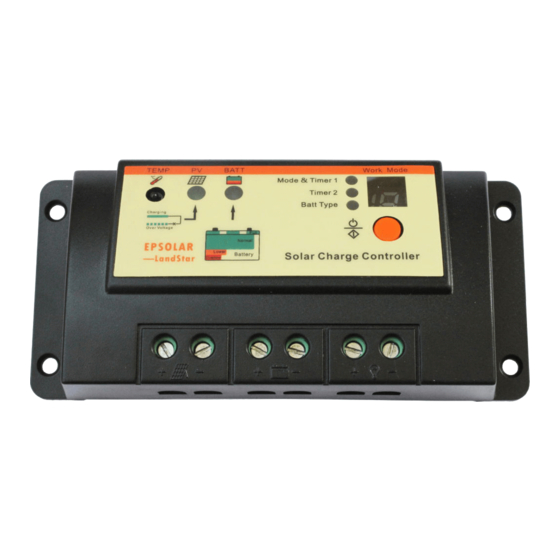
2.2 Product Features Figure 2-1 Land Star characteristics 1 –Temperature Sensor Measure ambient temperature and make temperature compensation for charging and discharging. – Charging status LED indicator A LED indicator that shows charging status and also indicates when battery voltage is higher than over voltage disconnect voltage. 3 –... -
Page 8: Installation Instructions
9 –Solar Module Terminals Connect solar modules. 10 –Battery Terminals Connect batteries. 11 –Load Terminals Connect loads. 3 Installation Instructions 3.1 General Installation Notes Read through the entire installation section first before beginning installation. Be very careful when working with batteries. Wear eye protection. Have fresh water available to wash and clean any contact with battery acid. - Page 9 WARNING: Risk of explosion! Never install the controller in a sealed enclose with flooded batteries! Do not install in a confined area where battery gassed can accumulate. Step 1: Choose Mounting Location Locate the controller on a vertical surface protected from direct sun, high temperature, and water.
-
Page 10: Wiring
3.3 Wiring NOTE: A recommended connection order has been provided for maximum safety during installation. NOTE: The controller is a common positive ground controller. CAUTION: Don’t connect the loads with surge power exceeding the ratings of the controller. CAUTION: For mobile applications, be sure to secure all wiring. - Page 11 Before battery is connected, make sure that battery voltage is greater than 6V so as to start up the controller. If system is 24V, make sure battery voltage is not less than 18V. System voltage can only be automatically recognized when controller start up for the first time.
- Page 12 If wiring the load connection to a load distribution panel, each load circuit should be fused separately. The total load draw should not exceed the load rated current of controller. Step 3: Solar wiring WARNING: Risk of electric shock! Exercise caution when handling solar wiring.
- Page 13 Step 4: Confirm Wiring Double-check the wiring in step1 through 3. Confirm correct polarity at each connection. Verify that all six terminals are tightened. Solar Module Load Fuse Fuse 150mm(5.9inches) Battery Figure 3-5 System wiring review Step 5: Confirm power on When battery power is applied and the controller starts up, the battery LED indicator will be green.
-
Page 14: Operation
4 Operation 4.1 PWM Technology (Series Pulse Width Modulation) The controller adopts the advanced series pulse width modulation (PWM) charging mode. With range of 0 to 100%, it can charge the battery quickly and stably under any condition of solar photovoltaic system. PWM charging mode use automatic conversion duty ratio pulses current to charge the battery. - Page 15 · Float Charge After the battery is fully charged in Boost voltage stage, the controller reduces the battery voltage to Float voltage set point. When the battery is fully recharged, there will be no more chemical reactions and all the charge current transmits into heat and gas at this time.
-
Page 16: Led Indicators
Certain types of batteries benefit from periodic equalizing charge, which can stir the electrolyte, balance battery voltage and complete chemical reaction. Equalizing charge increases the battery voltage, higher than the standard complement voltage, which gasifies the battery electrolyte. If the battery is being over discharged, the solar controller will automatically turn to equalize charging stage, and the equalize stage remain 120mins. - Page 17 Battery Status indicator GREEN ON when battery voltage in normal range GREEN SLOWLY FLASHING when battery full ORANGE ON when battery under voltage RED ON when battery over discharged Please refer to section 5 for troubleshooting. Battery status LED indicator Table 4-2 Color Indicator...
-
Page 18: Setting Operation
Setting Operation Sealed Setting indicator Load Status LED indicator Setting indicator Flooded Setting Indicator Setting button Figure 4-3 Setting operation indicating ·Load Work Mode Setting When the controller is powered on, press the setting button to control the load output. Press the button once, the ON/OFF status will be changed corresponding. -
Page 19: Protection, Troubleshooting And Maintenance
5 Protection, Troubleshooting and Maintenance 5.1 Protection · PV Array Short Circuit If PV array short circuit occurs, clear it to resume normal operation. · Load Overload If the load current exceeds the maximum load current rating, the controller will disconnect the load. Overloading must be cleared up through reapply power or pressing the setting button. -
Page 20: Troubleshooting
5.2 Troubleshooting Trouble Shooting Table 5-1 Faults Possible reasons Troubleshooting Charging LED Check that PV and battery indicator off array wire connections are correct during daytime disconnection and tight. when sunshine falls on PV modules properly. Green charging Battery voltage Check if battery voltage indicator higher than over... - Page 21 Sealed、Gel、 Too high When heat sink of the controller exceeds 85 ℃, Flooded temperature of indicator flashing controller the controller will simultaneously automatically cut input and output circuit. When the temperature below 75℃, the controller will resume to work Notes: No LED indicator. Measure battery voltage with multimeter.
-
Page 22: Maintenance
5.3 Maintenance The following inspections and maintenance tasks are recommended at least two times per year for best controller performance. Check that the controller is securely mounted in a clean and dry environment. Check that the air flow and ventilation around the controller is not blocked. Clear all dirt or fragments on the heat sink. -
Page 23: Warranty
6 Warranty The LandStar charge controller is warranted to be free from defects for a period of Two (2) years from the date of shipment to the original end user. We will, at its option, repair or replace any such defective products. •... -
Page 24: Technical Specifications
7 Technical specifications Electrical Parameters Table 7-1 Description Parameter Nominal System Voltage 12 / 24VDC Auto Maximum Battery Voltage LS1024 Rated Battery Current LS1524 LS2024 ≤0.26V Charge Circuit Voltage Drop ≤0.15V Discharge Circuit Voltage Drop ≤6mA Self-consumption Temperature Compensation Coefficient... - Page 25 Battery Voltage Parameters (temperature at 25℃) Table 7-3 Charging Parameters Battery charging Sealed Flooded setting Over Voltage Disconnect 16V; x2/24V 16V; x2/24V 16V; x2/24V Voltage Charging 15.5V;x2/24V 15.5V;x2/24V 15.5V;x2/24V Limit Voltage Over Voltage Reconnect 15V; x2/24V 15V; x2/24V 15V; x2/24V Voltage Equalize Charging...
- Page 26 Environmental parameters Parameter -35℃ ~ +55℃ Working temperature -35℃ ~ +80℃ Storage temperature ≤95% N.C. Humidity Enclosure IP30 LS1024 Mechanical parameters Table 7-5 Mechanical Parameter Parameter Overall dimension 140(5.51)x65(2.56)x34(1.34) mm/inches 130(5.12) x 45(1.77) mm/inches Mounting dimension Φ4.5 Mounting hole size...
-
Page 27: Annex: Mechanical Dimensions
Annex: Mechanical dimensions mm(inches) 130(5.12) 140(5.51) Figure1-1 LS1024 Dimensions 135(5.31) 144(5.67) Figure1-2 LS1524 & LS2024 Dimensions... - Page 30 Version number: V3.2...
- Page 32 BEIJING EPSOLAR TECHNOLOGY CO., LTD. Tel:+86-10-82894112 / 82894962 Fax:+86-10-82894882 E-mail:info@epsolarpv.com Website: www.epsolarpv.com...
Need help?
Do you have a question about the LS1024 and is the answer not in the manual?
Questions and answers