Table of Contents
Advertisement
Utility model patent NO.
EPSOLAR
201120064092.1
Tracer-3215RN
—— Maximum Power Point Tracking Solar Charge Controller
INSTRUCTION
MANUAL
Thank you very much for selecting our product!
This manual offers important information and suggestions with respect to
installation, use and troubleshooting, etc. Please read this manual carefully
before using the product and pay attention to the safety recommendations
in it.
Advertisement
Table of Contents
Troubleshooting

Related Manuals for Epsolar Tracer-3215RN


Summary of Contents for Epsolar Tracer-3215RN
- Page 1 Utility model patent NO. EPSOLAR 201120064092.1 Tracer-3215RN —— Maximum Power Point Tracking Solar Charge Controller INSTRUCTION MANUAL Thank you very much for selecting our product! This manual offers important information and suggestions with respect to installation, use and troubleshooting, etc. Please read this manual carefully before using the product and pay attention to the safety recommendations in it.
- Page 3 Tracer-3215RN —— Maximum Power Point Tracking Solar Charge Controller System Voltage 12 / 24VDC Rated Charge Current Rated Discharge Current Max. PV Input Voltage 150VDC Max. PV Input Power 12V System 390W 24V System 780W **Array voltage should never exceed maximum PV input voltage. Refer to the solar module documentation to determine the highest expected array Voc (open circuit voltage) as defined by the lowest expected ambient temperature for the system location.
-
Page 4: Table Of Contents
Contents 1 Important Safety Information ..........1 2 General Information ............. 2 2.1 Overview ..............2 2.2 Optional Accessories..........4 3 Installation Instructions ............5 3.1 General Installation Notes ........5 3.2 Mounting ..............5 3.3 Wiring ..............6 4 Operation ................9 4.1 MPPT Technology ........... -
Page 5: Important Safety Information
1 Important Safety Information Save These Instructions This manual contains important safety, installation and operating instructions for Tracer The following symbols are used throughout this manual to indicate potentially dangerous conditions or mark important safety instructions,please take care when meeting these symbols WARNING: Indicates a potentially dangerous condition. -
Page 6: General Information
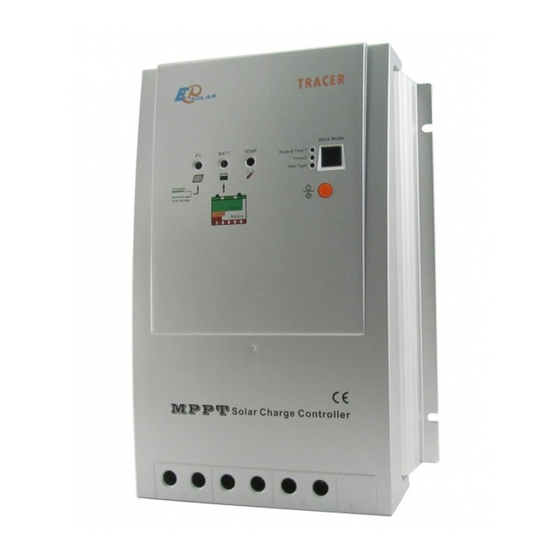
2 General Information 2.1 Overview Thank you for selecting the Tracer controller which represents advanced technology of our company The features are listed below: 12V / 24V auto recognition Advanced maximum power point tracking technology to optimize using the solar system Peak conversion efficiency of 97 %, high Tracking efficiency of 99% Very fast sweeping of the entire I-V curve, several seconds tracking speed... - Page 7 The features of Tracer controller: RJ45 Tracer Figure 2-1 Characteristics...
-
Page 8: Optional Accessories
1 – Charging Status LED Indicator An LED indicator that shows charging status and overvoltage of battery 2 – Battery Status LED Indicator An LED indicator that shows battery status or system errors 3 – Temperature Sensor Measure ambient temperature and make temperature compensation for charging and discharging 4 –... -
Page 9: Installation Instructions
3 Installation Instructions 3.1 General Installation Notes Read through the entire installation section first before beginning installation Be very careful when working with batteries Wear eye protection Have fresh water available to wash and clean any contact with battery acid Uses insulated tools and avoid placing metal objects near the batteries Explosive battery gasses may be present during charging Be certain there is sufficient ventilation to release the gasses... -
Page 10: Wiring
Step 4: Drill Holes Remove the controller and drill four sizeable holes in the marked locations Step 5: Secure Controller Place the controller on the surface and align the mounting holes with the drilled holes in step 4 Secure the controller in place using the mounting screws 3.3 Wiring NOTE: A recommended connection order has been provided for maximum safety during installation. - Page 11 Before connecting the battery, measure the battery voltage It must be over 9V to power the controller For 24V, the voltage must be greater than 18V to properly detect a 24V battery The 12/24V battery detection is automatic and the check is only performed at start-up Wire an in-line fuse holder no more than 150mm from the battery positive terminal Do not insert a fuse at this time Confirm the connection correct and then...
- Page 12 The Tracer can accept 12V, 24V nominal off-grid solar module arrays Grid –tie solar module(s) may be used if the open circuit voltage does not exceed the maximum solar input rating The solar module(s) nominal voltage must be equal to or greater than the nominal battery voltage Solar Module Figure3-3 Solar Module wiring...
-
Page 13: Operation
4 Operation 4.1 MPPT Technology The Tracer utilizes Maximum Power Point Tracking technology to extract maximum power from the solar module (s) The tracking algorithm is fully automatic and does not require user adjustment, Tracer technology will track the array maximum power point voltage (Vmp) as it varies with weather conditions, ensuring that maximum power is harvested from the array through the course of the day Current Boost... - Page 15 Tracer Figure 4-2 MPPT charging algorithm Bulk Charge In this stage, the battery voltage has not yet reached boost voltage and 100% of available solar power is used to recharge the battery Boost Charge When the battery has recharged to the Boost voltage setpoint, constant-voltage regulation is used to prevent heating and excessive battery gassing The Boost stage remains 120 minutes and then goes to Float Charge Every time when the controller is powered on, if it detects neither over discharged nor overvoltage, the charging will...
- Page 17 Charging Indicator The green LED indicator will light whenever sunlight is available for battery charging, the green charging LED will stay on in normal charging The charging LED indicator flashes when battery over voltage Please refer to Chapter 5 for troubleshooting Charging LED indicator Table4-1...
- Page 18 PV Overcurrent Display If the solar input current exceeds the maximum rating, the array will be disconnected automatically PV Overcurrent LED Display Table 4-4 Color Indication Operating State displays ―C‖ PV Overcurrent LED digital tube Load indicator When the load amp is 1 25times of rated current for 60 seconds, or the load amp is 1 5 times of rated current for 5 seconds (overload);...
- Page 21 Load work mode Table 4-6 Timer1 Digital Disable Dusk to Dawn, Load will be on all night Load will be on for 1 hour after ten minutes delay since sunset Load will be on for 2 hours after ten minutes delay since sunset Load will be on for 3 hours after ten minutes delay since sunset Load will be on for 4 hours after ten minutes delay since sunset Load will be on for 5 hours after ten minutes delay since sunset...
- Page 22 Load work mode Table 4-7 Timer2 LED Digital No Disable Load will be on for 1 hour before sunrise Load will be on for 2 hours before sunrise Load will be on for 3 hours before sunrise Load will be on for 4 hours before sunrise Load will be on for 5 hours before sunrise Load will be on for 6 hours before sunrise Load will be on for 7 hours before sunrise...
-
Page 23: Protections, Troubleshooting And Maintenance
5 Protections, Troubleshooting and Maintenance 5.1 Protection PV Array Short Circuit If PV array short circuit occurs, clear it to resume normal operation PV Overvoltage If PV Overvoltage occurs, the array will remain disconnected until the voltage falls safely below the maximum rating PV Overcurrent If PV Overcurrent occurs, the array will be disconnected automatically Load Overload... -
Page 24: Troubleshooting
5.2 Troubleshooting Trouble Shooting Table 5-1 Faults Possible reasons Troubleshooting Charging LED Check that PV and battery wire indicator off during array disconnection connections are correct and tight daytime when sunshine falls on PV modules properly Green charging Battery voltage Check if battery voltage over indicator higher than over... -
Page 25: Maintenance
5.3 Maintenance The following inspections and maintenance tasks are recommended at least two times per year for best controller performance Check that the controller is securely mounted in a clean and dry environment Check that the air flow and ventilation around the controller is not blocked Clear all dirt or fragments on the heat sink ... -
Page 26: Warranty
6 Warranty The Tracer charge controller is warranted to be free from defects for a period of TWO (2) years from the date of shipment to the original end user We will, at its option, repair or replace any such defective products •... -
Page 27: Technical Specifications
7 Technical Specifications • Electrical Parameters Description Parameter Nominal System Voltage 12VDC / 24VDC Auto work Rated Charge Current Rated Discharge Current Maximum Battery Voltage Max Solar Input Voltage 150VDC 12V / 390W Max PV input power 24V / 780W Self-consumption* <10mA(24V) ≤0 26V... - Page 28 • Threshold Voltage Description Parameter NTTV (Night Time Threshold Voltage) 5V; x2/24V DTTV (Day Time Threshold Voltage) 6V; x2/24V • Temp compensation Description Parameter Temperature Compensation -30mV/℃/12V(25℃ ref) Coefficient(TEMPCO)* * Compensation of equalize, boost, float and low voltage disconnect voltage. •...
- Page 32 Tracer Dimensions (mm)
- Page 34 Version number: V6 0...
- Page 36 BEIJING EPSOLAR TECHNOLOGY CO., LTD. Tel:010-82894112 / 82894962 Fax:010-82894882 E-mail:info@epsolarpv.com Website:www.epsolarpv.com...
Need help?
Do you have a question about the Tracer-3215RN and is the answer not in the manual?
Questions and answers
How do you set the remote
To set the remote for the Epsolar Tracer-3215RN:
1. Connect the MT-5 remote meter to the Tracer controller using the RJ45 communication interface.
2. The MT-5 displays system operating information, error messages, and diagnostics on a backlit LCD.
3. Use the large buttons on the MT-5 to navigate menus and view settings.
4. The MT-5 can be mounted flush in a wall or surface-mounted with the included frame and 2m cable.
No additional configuration steps are required beyond connecting the MT-5 to the RJ45 port.
This answer is automatically generated
Tracer-3215RN is good for lifepo4 battery? thanks