
Subscribe to Our Youtube Channel
Related Manuals for Epsolar LS0512R


Summary of Contents for Epsolar LS0512R
- Page 1 EPSOLAR LS0512R —— Solar Light Controller INSTRUCTION MANUAL Please read this manual carefully before using the product!...
- Page 3 LandStar LS0512R —— Solar Light Controller Nominal system voltage 12VDC Maximum PV input voltage Nominal charge / discharge current...
-
Page 4: Table Of Contents
Contents 1 Important Safety Information ........1 2 General Information ..........3 2.1 Product Overview ........3 2.2 Product Features .......... 5 3 Installation Instructions ..........7 3.1 Mounting ............7 3.2 Wiring ............10 4 Operation ..............13 4.1 Battery Charging Information .... -
Page 5: Important Safety Information
1 Important Safety Information Save These Instructions This manual contains important safety, installation and operating instructions. The following symbols are used throughout this manual to indicate potentially dangerous conditions or mark important safety instructions,please take care when meeting these symbols. WARNING: Indicates a potentially dangerous condition. -
Page 6: General Safety Information
General Safety Information Read all of the instructions and cautions in the manual before beginning installation. There are no user serviceable parts inside the controller. Do not disassemble or attempt to repair it. Install external fuses/breakers as required. ... -
Page 7: General Information
2 General Information 2.1 Product Overview Thank you for selecting LandStar series solar light controller that adopts the most advanced digital technique and operates fully automatically. The Pulse Width Modulation (PWM) battery charging can greatly increase the lifetime of battery. It has various unique functions and quite easy to use, such as: High efficient Series PWM charging, increase the battery lifetime and improve the solar system performance. - Page 8 The controller is for off-grid solar system, especially in solar light system, and protects the battery from being over charged by the solar module and over discharged by the loads. The charging process has been optimized for long battery life and improved system performance. The comprehensive self-diagnostics and electronic protection functions can prevent damage from installation mistakes or system faults.
-
Page 9: Product Features
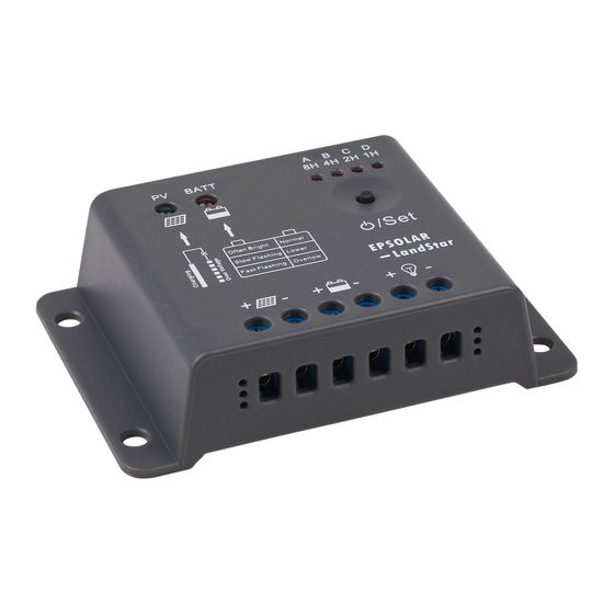
2.2 Product Features Figure 2-1 LandStar characteristics – Charging status LED indicator An LED indicator that shows charging status and also indicates when battery voltage is higher than over voltage disconnect voltage. 2 – Battery status LED indicator An LED indicator that shows battery status. 3 –... - Page 10 4 –Setting button Set load work mode (in manual mode used for load ON/OFF). 5 –Solar Module Terminals Connect solar modules. 6 –Battery Terminals Connect batteries. 7 –Load Terminals Connect loads.
-
Page 11: Installation Instructions
3 Installation Instructions 3.1 Mounting Read through the entire installation section first before beginning installation. Be very careful when working with batteries. Wear eye protection. Have fresh water available to wash and clean any contact with battery acid. Uses insulated tools and avoid placing metal objects near the batteries. - Page 12 NOTE: When mounting the controller, ensure free air through the controller heat sink fins. There should be at least 6 inches (150 mm) of clearance above and below the controller to allow for cooling. If mounted in an enclosure, ventilation is highly recommended.
- Page 13 150mm(5.9inches) Warm air 150mm(5.9inches) Cool air Figure 3-1 Mounting and cooling Step 3: Mark Holes Use a pencil or pen to mark the four (4) mounting hole locations on the mounting surface. Step 4: Drill Holes Remove the controller and drill 4mm holes in the marked locations. Step 5: Secure Controller Place the controller on the surface and align the mounting holes with the drilled holes in step 4.
-
Page 14: Wiring
3.2 Wiring NOTE: A recommended connection order has been provided for maximum safety during installation. NOTE: The controller is a common positive ground controller. CAUTION: Don’t connect the loads with surge power exceeding the ratings of the controller. CAUTION: For mobile applications, be sure to secure all wiring. - Page 15 Before battery is connected, make sure that battery voltage is greater than 6V so as to start up the controller. The load should be DC applicant with the same rated voltage as battery’s. Controller offers power to loads through the battery voltage. It is recommended that no less than 2 times rated current fuse is connected with battery and load.
- Page 16 Step 1: Wiring The recommended connection order has been provided as Figure3-2 indicated. Be sure the positive and negative polarity is correct and all terminals are tightened. Solar Module Load Fuse Fuse Battery Figure 3-2 System wiring review Step 2: Confirm power on When battery power is applied and the controller starts up, the battery LED indicator will be green.
-
Page 17: Operation
4 Operation 4.1 Battery Charging Information Figure 4-1 PWM Charging mode · Bulk Charge In this stage, the battery voltage has not yet reached boost voltage and 100% of available solar power is used to charge the battery. · Boost Charge When the battery has recharged to the Boost voltage setpoint, constant-current regulation is used to prevent heating and excessive battery gassing. - Page 18 · Float Charge After the battery is fully charged in Boost voltage stage, the controller reduces the battery voltage to Float voltage set point. When the battery is fully recharged, there will be no more chemical reactions and all the charge current transmits into heat and gas at this time.
- Page 19 NOTE: Equipment damage! Equalization may increase battery voltage to the level damaging to sensitive DC loads. Ensure that all load allowable input voltages are greater than the equalizing charging set point voltage. NOTE: Equipment damage! Over-charging and excessive gas precipitation may damage the battery plates and activate material shedding on them.
-
Page 20: Led Indicators
Indicators 4.2 LED Charging indicator Battery indicator Setting button Figure 4-2 LED indicators Charging status indicator GREEN ON whenever sunlight is available for battery charging, GREEN FAST FLASHING when battery over voltage. Please refer to section 5 for troubleshooting. - Page 21 Charging Status LED indicator Table 4-1 Color Indicator Charging Status Green On Solid Charging Green Fast Flashing Battery over voltage Battery status indicator RED ON when battery voltage in normal range RED SLOWLY FLASHING when battery under voltage RED FAST FLASHING when battery over discharged Please refer to section 5 for troubleshooting.
-
Page 22: Setting Operation
Load status LED indicator Table 4-3 Color LED digital tube Load status 8H、4H、2H、1H Flashing together Overload or short circuit Setting Operation . Load Control Settings 1. Dusk to Dawn When solar module voltage goes below the point of NTTV (Night Time Threshold Voltage) at sunset, the controller will recognize the starting voltage and turn on the load after 10 minutes delay. - Page 23 3. Test mode This mode is the same as Dusk to Dawn. But there is no 10 minutes delay when controller recognizes the starting voltage. When below the starting voltage, the controller will turn on the load, if higher, it will turn off load.
- Page 24 Load work mode Table 4-4 Work mode Dusk to Dawn, ○ ○ ○ × load will be on all night Load will be on for 1 hour ○ × × × after 10 minutes delay since sunset Load will be on for 2 hours ○...
- Page 25 Load will be on for 10 hours ○ ○ × × after 10 minutes delay since sunset Load will be on for 11 hours ○ ○ ○ × after 10 minutes delay since sunset Load will be on for 12 hours ○...
-
Page 26: Protections, Troubleshooting And Maintenance
5 Protection, Troubleshooting and Maintenance 5.1 Protection · Load Overload If the load current exceeds the maximum load current rating, the controller will disconnect the load. Overloading must be cleared up through reapply power or pressing the setting button. · Load Short Circuit Fully protected against load wiring short-circuit. -
Page 27: Troubleshooting
5.2 Troubleshooting Trouble Shooting Table 5-1 Faults Possible reasons Troubleshooting Charging LED Check that PV and indicator off during array battery wire daytime when disconnection connections sunshine falls on correct and tight. PV modules properly. Green charging Battery voltage Check battery LED indicator fast higher than over... - Page 28 Over load Overload: Please 8H、4H、2H、1H or short circuit reduce the load and press the button once, indicator flashing the controller will together resume to work after Short circuit: when the first short-circuit occurs, the controller will automatically resume to work after 10s;...
-
Page 29: Maintenance
5.3 Maintenance The following inspections and maintenance tasks are recommended at least two times per year for best controller performance. Check that the controller is securely mounted in a clean and dry environment. Check that the air flow and ventilation around the controller is not blocked. -
Page 30: Warranty
Confirm that all the terminals have no corrosion, insulation damaged, high temperature or burnt/discolored sign, tighten terminal screws to the suggested torque. Inspect for dirt, insects and corrosion, and clear up. Check and confirm that lightning arrester is in good condition. Replace a new one in time to avoid damaging of the controller and even other equipments. - Page 31 • Claim procedure: Before requesting warranty service, check the Operation Manual to be certain that there is a problem with the controller. Return the defective product to us with shipping charges prepaid if problem cannot be solved. Provide proof of date and place of purchase. To obtain rapid service under this warranty, the returned products must include the model, serial number and detailed reason for the failure, the module type and size, type of batteries and system loads.
-
Page 32: Technical Specifications
7 Technical specifications Electrical Parameters Table 7-1 Description Parameter Nominal System Voltage Max. batt. Volt. to the controller Rated Battery Current ≤0.26V Charge Circuit Voltage Drop ≤0.15V Discharge Circuit Voltage Drop ≤6mA Self-consumption Threshold Voltage Parameters Table7-2 Description Parameter NTTV(Night Time Threshold Voltage) 5V;... - Page 33 Temperature Compensation Coefficient Table7-3 Description Parameter Temperature Compensation -30mV/℃/12V(25℃ ref) Coefficient(TEMPCO)* * Compensation of equalize, boost, float and low voltage disconnect voltage...
- Page 34 (temperature at 25℃) Battery Voltage Parameters Table 7-4 Charging Parameters Battery charging setting Sealed Over Voltage Disconnect Voltage Charging Limit Voltage 15.5V Over Voltage Voltage reconnect 14.6V Equalize Charging Voltage 14.4V Boost Charging Voltage 13.8V Float Charging Voltage Boost Reconnect Charging 13.2V Voltage Low Voltage Reconnect Voltage...
- Page 35 Environmental parameters Table 7-5 Environmental parameters Parameter -35℃ to +55℃ Working temperature -35℃to +80℃ Storage temperature Humidity 10%-90% NC Enclosure IP30 Mechanical Parameters Table 7-6 Mechanical Parameter Parameter Overall dimension 97(3.82)x66(2.6)x25(0.98) mm/inches Mounting dimension 86(3.39) x 44(1.73) mm/inches Φ5 Mounting hole size Terminal 2.5mm Net weight...
- Page 36 mm(inches) 97(3.82) 86(3.39) Dimensions...
- Page 38 Version number: V6.0...
- Page 40 BEIJING EPSOLAR TECHNOLOGY CO., LTD. Tel:010-82894112 / 82894962 Fax:010-82894882 E-mail:info@epsolarpv.com Website: www.epsolarpv.com...
Need help?
Do you have a question about the LS0512R and is the answer not in the manual?
Questions and answers