Table of Contents
Advertisement
Quick Links
Advertisement
Table of Contents

Related Manuals for Aktakom ATK-2209


Summary of Contents for Aktakom ATK-2209
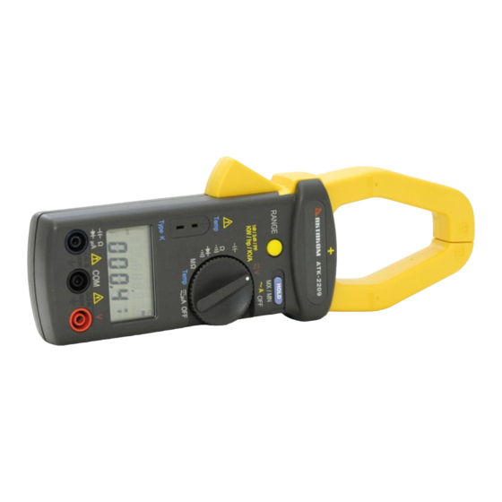
- Page 1 ATK-2209 Clamp Meter User’s Manual www.tmatlantic.com...
-
Page 2: Table Of Contents
CONTENTS Title Page SAFETY INFORMATION ............. 1 TECHNICAL SPECIFICATIONS ..........2 2-1 Environment Conditions .............. 2 2-2 Maintenance................2 2-3 Features ..................2 2-4 General Specifications ..............4 2-5 Measurement Specifications ............4 III. PARTS & CONTROLS ..............7 3-1 Description of Parts & Control ............. 7 OPERATING INSTRUCTION ............ -
Page 3: Safety Information
I. SAFETY INFORMATION Read the following safety information carefully before operating the meter. To avoid damages to the instrument, do not exceed the maximum limits of the input values shown in the technical specification tables. Do not use the meter or test leads if they look damaged. ... -
Page 4: Technical Specifications
II. TECHNICAL SPECIFICATIONS 2-1 Environment Conditions : Installation categories III Pollution degree 2 Altitude up to 2000 meters Indoor use only Relatively humidity 80% max. Operation ambient 0 ~ 50℃ 2-2 Maintenance : Repairs or servicing not covered in this manual should only be performed by qualified personnel. - Page 5 2-3-3 Function : True RMS. ACV, ACA. 9999 counts dual display LCD with unit sign. Trms ACA : 0.01A to 999.9A. (Auto/Manual : 99.99A, 999.9A ) Trms ACV : 2.0mV to 600.0V. (Auto/Manual : 999.9mV, 9.999V, 99.99V 600.0V) 1φ/3φ...
-
Page 6: General Specifications
2-4 General Specifications : Maximum voltage between any terminal and earth ground : 600Vrms. Numerical dual display : Dual display 4 digits LCD maximum reading 9999.(10,000 Count Reading) Battery life : approx. 32hr Low battery indication : The is displayed when the battery voltage drops below the operating voltage. - Page 7 µA Trms : (AC+DC) (Burden Voltage : 5mV/µA) Range Resolution Accuracy Sensitivity Overload Protection 10nA 0.20µA 99.99µA 600V ±1% ±20dgts 100nA 2.0µA 999.9µA AC Voltage (50Hz to 400Hz) : Trms Overload Range Resolution Accuracy Sensitivity Protection ±1% ±20dgts (50, 60Hz) 999.9mV 0.1mV 2.0mV...
- Page 8 Diode (Continuity<40mV) : Range Resolution Accuracy Overload Protection 2.000V 600V ±2% ±1dgt Temperature (K-Type thermocouple) : Range Resolution Accuracy Overload Protection -50 ℃ to 900 ℃ 0.1 ℃ ±1%±1 ℃ or 60V -58 ℉ to 1000 ℉ 0.1 ℉ ±1% ±2 ℉ 1φ/3φ...
-
Page 9: Parts & Controls
PARTS & CONTROLS III. 3-1 Description of Parts & Control MX / MN Temp Type K WL123 3 3W hp Hz 3 4W h:mm:s lead ¢X F KVAR ¢X KVAR CAT III CAT III 600V 600V (Figure-1) www.tmatlantic.com... - Page 10 (1). Transformer jaws (+ mark face to source) : Pick up the AC current flowing through the conductor. (2). Jaw opening trigger. (3). Data Hold (MX/MN) key : a. Data Hold mode : Press it to hold the measured value. Press again to release.
-
Page 11: Operating Instruction
Press RANGE key to select ℃ or ℉ . (6). Temperature input jack. Only Type K thermocouple input is accepted. (7). LCD display : 4 digits with indications for measurement values, unit symbols, decimal point, polarity, over range, and low battery ; etc. (8). -
Page 12: Ac Current Measurement
4-2 AC Current Measurement Set the rotary switch to the "~A" position. Press the trigger to open the jaw and fully close the conductor. NOTE The sensitivity for current frequency measurement is 6A, and the frequency range is 40 ~ 400Hz. If the frequency is less than 40 Hz, the LCD may show .Hz . -
Page 13: 3Φ3W Ac Power Kw, Hp, Kva, Kvar, Pf (Power Factor) Andθ
= cos θ ( θ =Phase Angle) HP (Horse Power) : HP = 746 Watts KVA (Apparent Power) : KVA = (V A)/1000 KVAR (Reactive Power) : KVAR= =KVA sin θ (KVA) − (KW) NOTE 1. The "+" sign printed on Panel must face to the power source for accurate measurement. - Page 14 MX / MN Temp Type K WL12 3 3W CAT III CAT III 600V 600V WL12 3 3W WL12 3 3W CAT III CAT III 600V 600V (Figure-3) Second, measure W (refer to figure 4). TS(L3L2) a. Disconnect the test probe from the phase where jaws is clamp on in previous measurement.
- Page 15 MX / MN Temp Type K WL 23 3 3W CAT III CAT III 600V 600V WL 23 3 3W WL 23 3 3W CAT III CAT III 600V 600V (Figure-4) The power clamp will process those two sets of data (W ), and show the result on the LCD.
- Page 16 φ φ φ Set the rotary switch to other position exit this mode and clear the stored data. NOTE Once a phase is selected as COM, users can not change this selection in the subsequent measurement. For example, if S (or L2) phase is selected, S (or L2) phase is always connected to the COM during measurement of W (or W...
-
Page 17: 3Φ4W Ac Power Kw, Hp, Kva, Kvar, Pf (Power Factor) And Θ(Phase Angle) Measurement
θ 4-5 3 φ 4W AC Power KW, HP, KVA, KVAR, PF (Power Factor) and (Phase Angle) Measurement First, measure W (refer to figure 6). R(L1) a. Set the rotary switch to the “ V ” position. b. Press and hold down the “RANGE” key then set the rotary switch to “KW/KVA”... - Page 18 c. Clamp the phase where test probe is connected to (eg. S or L2 phase) d. The power clamp will automatically select proper range. e. Wait until the reading is stable (about 6 seconds), press the “HOLD” key and W symbol will disappear.
- Page 19 MX / MN Temp Type K WL 3 3 4W CAT III CAT III 600V 600V WL 3 3 4W WL 3 3 4W CAT III CAT III 600V 600V (Figure-8) The power clamp will process these three sets of data (W ) and show the result on the LCD.
-
Page 20: Resistance & Continuity Measurement
If willing to read the details of that singly data record, please “HOLD” key to select desired WL1, WL2, WL3 or WL123 display then press “RANGE” key to select KW+HP (Horse Power), KW+PF (Power Factor), KW+KVAR, KVA+ θ (Phase Angle) or A+V 5 types display. ... -
Page 21: Capacitance Measurement
4-7 Capacitance Measurement Fully discharge the capacitor being tested, will speed test response time. Insert the test leads into the input jack. (Black to COM and Red to Set rotary switch to the " " position. Connect the red test lead to the anode side and black test lead to the cathode side of the capacitor being tested. -
Page 22: Battery Replacement
V. BATTERY REPLACEMENT WARNING To prevent electrical hazard or shock, turn off clamp meter and disconnect test leads before removing back cover. As battery power is not sufficient, LCD will display . Replacement with one new battery type 9 V is required. ...
Need help?
Do you have a question about the ATK-2209 and is the answer not in the manual?
Questions and answers