Table of Contents
Advertisement
Quick Links
Advertisement
Table of Contents

Related Manuals for Aktakom ACM-2348


Summary of Contents for Aktakom ACM-2348
- Page 1 DC+AC TRMS WATT CLAMP METER ACM-2348 OPERATING INSTRUCTION www.tmatlantic.com...
-
Page 2: Safety Notes
Safety International Safety Symbols This symbol, adjacent to another symbol or terminal, indicates the user must refer to the manual for further information. This symbol, adjacent to a terminal, indicates that, under normal use, hazardous voltages may be present Double insulation SAFETY NOTES Do not exceed the maximum allowable input range of any function... - Page 3 or death. Read and understand this user manual before operating the meter. Always remove the test leads before replacing the battery. Inspect the condition of the test leads and the meter itself for any damage before operating the meter. Repair or replace any damage before use.
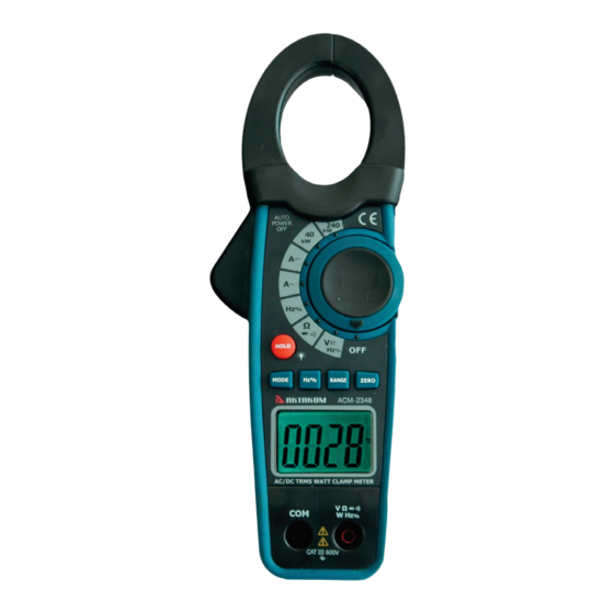
- Page 4 Meter Description 1. Current clamp 2. Clamp trigger 3. Data Hold and Backlight button 4. Mode select button 5. Hz/% button 6. LCD display 7. COM input jack 8. Rotary Function swith 9. ZERO button 10. Range select button H z% 11.
-
Page 5: Specifications
HOLD Data Hold mode 9.KW, P,m,V,A,K,M, , Units of measure list Specifications Function Range & Accuracy Resolution reading) ± (1.8% + 5 DC Current 1000 ADC digits ± (2.0% + 5 AC Current 1000 AAC digits 400.0 mVDC ± (0.8% + 3 digits) 4.000 VDC DC Voltage 40.00 VDC... - Page 6 r(1.2% reading + 2 Duty Cycle 0.5 to 99.0% digits) Pulse width: 100μs - 100ms, Frequency: 5.000Hz ~ 100.0kHz AC WATT 40KW ± (2.5% + 5 digits) (0-250 V,0- 400A, 50/60Hz TRMS) AC WATT 240KW ± (2.5% + 5 digits) (0-600V,0- 400A, 50/60Hz...
- Page 7 Overrange Indication “OL” is displayed Measurements Rate 2 per second, nominal Input Impedance 7.8M: (VDC and VAC) Display 4000 counts LCD AC Current 50/60Hz True RMS (AAC) AC Voltage bandwidth 50/60Hz True RMS (VAC) Operating Temperature 14 to 122 F (-10 to 50 Storage Temperature -14 to 140 F (-30 to 60...
- Page 8 Operation NOTICES: Read and understand all warning and precaution statements listed in the safety section of this operation manual prior to using this meter. Set the function select switch to the OFF position when the meter is not in use. DC+AC Power/Watt Measurements current Voltage...
-
Page 9: Dc/Ac Current Measurements
Select the range to Current AC or DC, and check the current reading. Select appropriate Watt range 40KW(0-250V,0-400A) or 240KW (0-600V,0-400A). Read the value shown on LCD in KW (AC+DC). DC/AC Current Measurements WARNING: Ensure that the test leads are disconnected from the meter before making current... - Page 10 Resistance and Continuity Measurements Insert the black test lead into the negative COM terminal and the red test lead into the positive terminal. •))) : position. Set the function switch to the Use the multifunction MODE button to select resistance. Touch the test probe tips across the circuit or component under test.
- Page 11 Capacitance Measurements WARNING: To avoid electric shock, disconnect power to the unit under test and discharge all capacitors before taking any capacitance measurements. Remove the batteries and unplug the line cords. 1. Set the rotary function switch to the cap position. 2.
-
Page 12: Manual Ranging
The backlight function illuminates the display and is used when the ambient light to too low to permit viewing of the displayed readings. Press the (HOLD) button for one second to turn the backlight on and press the button a second time to turn the backlight off.
Need help?
Do you have a question about the ACM-2348 and is the answer not in the manual?
Questions and answers