Table of Contents
Advertisement
Quick Links
Advertisement
Table of Contents

Related Manuals for Aktakom ATK-2021B


Summary of Contents for Aktakom ATK-2021B
- Page 1 U s e r m a n u a l C l a m p m e t e r A Т K - 2 0 2 1 B www.tmatlantic.com...
- Page 2 EN 61010-2-032 CAT II 600V CAT III 300V Pollution Degree 2 SYMBOLS showed on the clamp meter or in this manual: Caution, risk of danger. Refer to accompanying documents Caution, risk of electric shock. Double Insulation Application around and removal from HAZARDOUS LIVE conductors is permitted.
- Page 3 Overvoltage Category I (CAT I): Equipment for connection to circuits in which measures are taken to limit the transient overvoltages to an appropriate low level. Overvoltage Category II (CAT II): Energy-consuming equipment to be supplied from the fixed installation. Overvoltage Category III (CAT III): Equipment in fixed installations.
-
Page 4: Table Of Contents
TABLE OF CONTENTS 1. Features ......................2 2. Panel Description ..................... 3 3. Operation Instructions..................6 3.1. DC/AC Current Measurements............. 6 3.2. DC/AC Voltage Measurements............. 7 3.3. Capacitance Measurement..............8 3.4. Temperature Measurement..............9 3.5. Resistance Measurement..............10 3.6. Continuity Test..................10 3.7. -
Page 5: Panel Description
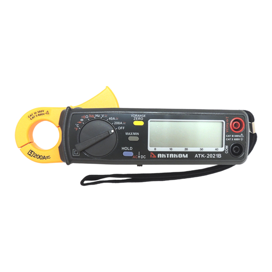
2. Panel Description 1. Transformer Jaw This is used to pick up current signal. To measure DC/AC current, conductor must be enclosed by the jaw. 2. Transformer Trigger This is used to open the jaw. 3. Function Selector Switch This is used to select the function user desired, such as DCA, ACA, DCV, ACV, Hz, Ohm and Continuity. - Page 6 updated. Press again, maximum value shall be displayed and updated. Zero function will be disabled if MAX/MIN is enabled. This button is not available in duty, hz, continuity, diode or capacitance function. 7. VΩRANGE Zero/Relative Button On voltage or ohm function, press this button to select manual range. On other functions, once this button is pressed, the current reading shall be set to zero and be used as a zero reference value for all other subsequent measurement.
- Page 7 18. Hand Strap Put your hand through the hole of hand strap to avoid accidental drop of the clamp meter. www.tmatlantic.com...
-
Page 8: Operation Instructions
3. Operation Instructions 3.1. DC/AC Current Measurements WARNING : Make sure that all the test leads are disconnected from the meter's terminals for current measurement. 3.1.1 DC Current a. Set the rotary switch at 40A or 200A and move the sliding switch to DC b. -
Page 9: Dc/Ac Voltage Measurements
3.1.2. AC Current a. Set the rotary switch at 40A or 200A and move the sliding switch to b. Press the trigger to open the jaw and fully enclose the conductor to be measured. No air gap is allowed between the two half jaws. c. -
Page 10: Capacitance Measurement
b. Insert the test leads into the input jack. c. Connect the test prods of the test leads in PARALLEL to the circuit to be measured. d. Read the measured value from the LCD display. 3.3. Capacitance Measurement a. Plug the adapter into the terminal b. -
Page 11: Temperature Measurement
3.4. Temperature Measurement a. Plug the adapter into the terminal b. Insert the K-type thermal couple into the adapter c. Read the temperature from LCD. WARNING : Before taking any in-circuit resistance measurement, remove power from the circuit being tested and discharge all the capacitors. www.tmatlantic.com... -
Page 12: Resistance Measurement
3.5. Resistance Measurement 3.5.1. Set the rotary switch at Ω . 3.5.2. Insert the test leads into the input jack. 3.5.3. Connect the test prods of the test leads to the two ends of the resistor or circuit to be measured. 3.5.4. -
Page 13: Relative Reading Measurements
3.10. Relative Reading Measurements The zero button also can be used to make a relative measurement. Once the button is pushed, the current reading is set to zero and a zero symbol shall be displayed on LCD. All the subsequent measurement shall be displayed as a relative value with respect to the value being zeroed. -
Page 14: Specifications(23°C ± 5°C )
4. Specifications(23°C ± 5°C ) DC Current: Range Resolution Accuracy Overload Protection 40 A 10mA ±1.5%±2dgts DC 400A 0-150 A 100mA ±1.5%±2dgts DC 400A 150-200 A 100mA ±2.2%±2dgts DC 400A AC Current: Range Resolution Accuracy Overload Protection 50/60 Hz 40 - 1KHz 10mA ±1.5%±3dgts ±2.0%±4dgts... - Page 15 Resistance ( Ω): (open voltage 0.4V) Range Resolution Accuracy Overload Protection ±1.5%±2dgts AC 600V 400 Ω 0.1 Ω ±1.5%±2dgts AC 600V 4K Ω 1 Ω ±1.5%±2dgts AC 600V 40K Ω 10 Ω ±1.5%±2dgts AC 600V 400K Ω 100 Ω ±1.5%±2dgts AC 600V 4M Ω...
- Page 16 Diode Test: Range Resolution Accuracy Overload Protection 0 – 1.999V 0.001V ±2.5%±5dgts AC 600V Conductor Size: 23mm max. (approx.) Battery Type: two 1.5V SUM-3 Display: 3 3/4 LCD with 40 seg. Bargraph Range Selection: manual Overload Indication: Power Consumption: 10 mA (approx.) Low battery Indication: Sampling Time: 3 times/sec.(display)
-
Page 17: Battery Replacement
5. Battery Replacement When the low battery symbol is displayed on the LCD or LCD display is dark, replace the old batteries with two new batteries. 5.1. Turn the power off and remove the test leads from the clamp meter. 5.2.
Need help?
Do you have a question about the ATK-2021B and is the answer not in the manual?
Questions and answers