Table of Contents
Advertisement
Quick Links
Advertisement
Table of Contents

Related Manuals for Aktakom ATK-2001


Summary of Contents for Aktakom ATK-2001
- Page 1 U s e r m a n u a l C l a m p m e t e r A Т K - 2 0 0 1 www.tmatlantic.com...
- Page 2 EN 61010-2-032 CAT II 600V CAT III 300V Pollution Degree 2 SYMBOLS showed on the clamp meter or in this manual: Caution, risk of danger. Refer to accompanying documents Caution, risk of electric shock. Double Insulation Overvoltage Category I (CAT I): Equipment for connection to circuits in which measures are taken to limit the transient overvoltages to an appropriate low level.
-
Page 3: Table Of Contents
TABLE OF CONTENTS 1. Features 2. Panel Description 3. Operation Instructions 3.1. DC/AC Current Measurements 3.2. DC/AC Voltage Measurements 3.3. Relative Reading Measurements 3.4. Holding the LCD Reading 3.5. Finding the MAX/MIN Value 3.6. To Recover from Auto-Power-Off 4. Specifications 5. -
Page 4: Panel Description
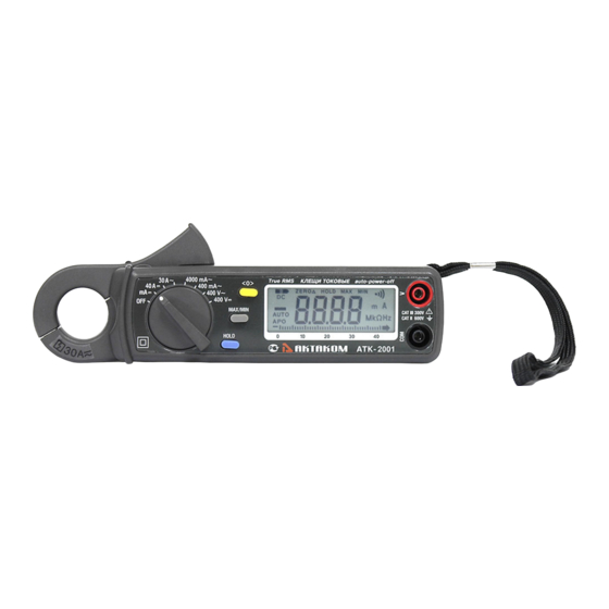
2. Panel Description 1. Transformer Jaw This is used to pick up current signal. To measure DC/AC current, conductor must be enclosed by the jaw. 2. Transformer Trigger This is used to open the jaw. 3. Function Selector and On/Off Switch This is used to select the function user desired, such as DCA, ACA, DCV, ACV. - Page 5 for the DC current measurement. The Zero/Relatiive function will be disabled if the MAX/MIN button is enabled. 7. LCD This is a 3 3/4 digit Liquid Crystal Display with maximum indication of 3999. Function symbols, units, bargraph, sign, decimal points, low battery symbols, max/min symbols, and zero symbol are included.
-
Page 6: Operation Instructions
3. Operation Instructions 3.1. DC/AC Current Measurements WARNING: Make sure that all the test leads are disconnected from the meter's terminals for current measurement. 3.1.1. DC Current a. Set the rotary switch at mA DC or 40A DC. b. Push the zero button to adjust the reading to zero. Due to the high sensitivity of the clamp meter, must zero in the same direction as in measurement to avoid interference by external magnetic field. -
Page 7: Dc/Ac Voltage Measurements
3.2. DC/AC Voltage Measurements WARNING: Maximum input for DC V is 600, and for AC V is 600. Do not attempt to take any voltage measurement that exceeds the limits. Exceeding the limits could cause electrical shock and damage to the clamp meter. 3.2.1. -
Page 8: Holding The Lcd Reading
button is pushed, the current reading is set to zero and a zero symbol shall be displayed on LCD. All the subsequent measurement shall be displayed as a relative value with respect to the value being zeroed. Press the zero button again to return to normal mode. -
Page 9: Specifications
4. Specifications (23 ° C±5 ° C) DC Current Range Resolution Accuracy Overload Protection mA (0-4A) ±2.0%±3dgts DC 40A 10mA ±2.0%±3dgts DC 100A 10mA ±2.5%±3dgts DC 100A AC Current (True RMS, Crest Factor < 3) Accuracy Overload Protection Range Resolution 50/60 Hz 40 - 100Hz 400mA... - Page 10 Indoor Use Conductor Size: 23mm max. (approx.) Battery Type: two 1.5V SUM-3 Display: 3 3/4 LCD with 40 seg. bargraph Range Selection: manual Overload Indication: Power Consumption: 15 mA (approx.) Low battery Indication: Sampling Time: 3 times/sec. (display) 30 times/sec. (bargraph) -10 °...
-
Page 11: Battery Replacement
5. Battery Replacement When the low battery symbol is displayed on the LCD, replace the old batteries with two new batteries. 5.1. Turn the power off and remove the test leads from the clamp meter. 5.2. Remove the screw of the battery compartment. 5.3.
Need help?
Do you have a question about the ATK-2001 and is the answer not in the manual?
Questions and answers