Table of Contents
Advertisement
Quick Links
Advertisement
Table of Contents

Related Manuals for Aktakom ATK-2040


Summary of Contents for Aktakom ATK-2040
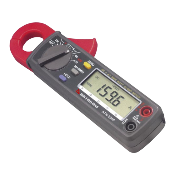
- Page 1 ATK-2040 AC/DC TRMS Watt Clamp Meter Users Manual www.tmatlantic.com...
- Page 2 EN 61010-2-032 CAT II 600V, CAT III 300V Pollution Degree 2 SYMBOLS showed on the clamp meter or in this manual: Caution, risk of danger. Refer to accompanying documents Caution, risk of electric shock. Double Insulation Application around removal from HAZARDOUS LIVE conductors is permitted.
- Page 3 Please follow the following instructions carefully for safe operation. ■ NEVER use the clamp meter for Voltages higher than 600V. ■ DO NOT hold the clamp meter beyond its tactile barrier. ■ DO NOT use the clamp meter and accessories if they look damaged. ■...
-
Page 4: Table Of Contents
TABLE OF CONTENTS I.Features II. Panel Description III.Operation Instructions A. DC/AC Current Measurements B. DC/AC Voltage Measurements C. AC+DC Power/Watt Measurement D. Frequency (Hz) Measurement E. Relative Reading Measurements F. Holding the LCD Reading G. Finding the MAX/MIN Value H. To Recover from Auto-Power-Off IV.Specifications V.Battery Replacement VI.Maintenance &... -
Page 5: Iii.operation Instructions
This is used to select the function user desired, such as DCA, ACA, DCV, ACV, Hz, Ohm and Continuity. 4. Data Hold Button Once this button is pushed, reading shall be held on the LCD. Press again to release it. This button is also used to recover from auto-power-off. -
Page 6: Dc/Ac Voltage Measurements
WARNING: Make sure that all the test leads are disconnected from the meter's terminals for current measurement. 1. DC Current a. Set the rotary switch at 400A DC. b. Push the zero button to adjust the reading to zero. c. Press the trigger to open the jaw and fully enclose the conductor to be measured. No air gap is allowed between the two half jaws. -
Page 7: Ac+Dc Power/Watt Measurement
1. DC Voltage a. Set the rotary switch at V DC. b. Insert the test leads into the input jack. c. Connect the test prods of the test leads in PARALLEL to the circuit to be measured. d. Read the measured value from the LCD display. 2. -
Page 8: Holding The Lcd Reading
function is disabled if MAX/MIN function is enabled. Please watch for symbol displayed on LCD. NOTE: 1. The ZERO button is disabled if Hz function is selected. 2. LCD displays relative numerical value without bargraph. F. Holding the LCD Reading Press the HOLD button, then the reading shall be hold and kept on LCD. -
Page 9: Iv.specifications
IV. Specifications(23 ° C±5 ° C) AC+DC Watt Range Resolution Accuracy Remarks AC 40KW ±1.5%±3dgts 1-250V, 1-400A, PF 0.6 -1, 50/60Hz, Vpeak < 360V AC 240KW 100W ±1.5%±3dgts 1-600V, 1-400A, PF 0.6-1, 50/60Hz, Vpeak < 850V AC 40KW ±2.5%±3dgts 1-250V, 1-400A, PF 0.6 -1, 40-100Hz, Vpeak < 360V AC 240KW 100W ±2.5%±3dgts... -
Page 10: V.battery Replacement
Weight: 190g (battery included) Accessories: Carrying bag x 1 Users manual x 1 1.5V battery x 2 V. Battery Replacement When the low battery symbol is displayed on the LCD, replace the old batteries with two new batteries. A. Turn the power off and remove the test leads from the clamp meter. B.
Need help?
Do you have a question about the ATK-2040 and is the answer not in the manual?
Questions and answers