Table of Contents
Advertisement
Quick Links
Advertisement
Table of Contents

Related Manuals for Aktakom ATT-8509


Summary of Contents for Aktakom ATT-8509
- Page 1 ATT-8509 Electromagnetic Field Meter User’s Manual www.tmatlantic.com...
-
Page 2: Table Of Contents
TABLE OF CONTENTS 1. FEATURES..............1 2. APPLICATIONS............2 3. SAFETY INSTRUCTIONS..........2 4. SPECIFICATIONS............4 5. FRONT PANEL DESCRIPTION........7 6. MEASUREMENT CONSIDERATION........ 8 7. MEASURING PROCEDURE..........9 7-1 Buttons instructions..........9 7-2 Symbols & units of display........10 7-3 Unit Selection............11 7-4 Frequency Team Of Selection........ 11 7-5 To see the individual axis' measuring EMF value..11 7-6 Alarm Limit Setting and Alarm start......12 7-7 Data Hold.............13... - Page 3 8. INTERIOR SETTING MODE.......... 19 8-1 Check Memory Space..........20 8-2 Clear Memory............20 8-3 Date/Time Setting..........20 8-4 Sample Time Setting..........21 8-5 Auto Power Off Default Setting....... 21 8-6 Escape from the SETTING function......21 9. RS232 PC SERIAL INTERFACE........22 10. BATTERY REPLACEMENT..........24 11.
-
Page 4: Features
1. FEATURES * 3 Axis probe. * Radio frequency electromagnetic field tester. * Wide measuring frequency ranges, 100 KHz to 3 GHz. * EMF-839 is used for broadband devices of monitoring the wide range radio frequency electromagnetic field value. * For precision measurement consideration, the meter is included two probes : EP-04L ( Low frequency Probe, 100 KHz to 100 MHz ) EP-03H ( High frequency Probe, 100 MHz to 3 GHz ) -
Page 5: Applications
2. APPLICATIONS This meter is specially developed for measuring or monitoring electromagnetic field, for example: cell-phone station, hospital equipment, radar , micro-wave oven, radiation work, TV antenna , Radio station , welding equipment , baking- equipment, television , computer , factory, laboratory , and other environment...etc. - Page 6 * Complete answers to any of these and related " Prudent Avoidance " as stated by the Environmental Protection Agency(EPA) USA is recommended. * According to ICNIRP of reference levels to time-varying electromagnetic fields, The E-field strength levels are: General public Frequency range e-field strength (V/m) 3 to 150 kHz...
-
Page 7: Specifications
4. SPECIFICATIONS 4-1 General Specifications Circuit Custom one-chip of microprocessor LSI circuit. Display LCD size : 58 mm x 34 mm. Measurement V/m, mW/cm^2, W/m^2. Unit Accuracy < 2 dB. Probe structure 3 Axis. Probe Type EP-03H : 100 MHz to 3 GHz. Selection EP-04L : 100 kHz to 100 MHz. - Page 8 Peak Hold To latch the peak measurement value. Alarm Setting Buzzer will sound when display over the setting value. Sampling Time Approx. 1 second. Low Battery When display show Low battery Indicator Indicator, it should change the batteries. Data Output RS 232 PC serial interface.
- Page 9 4-2 Electrical Specifications ( 23 ± 5 ℃ Strength Range Resolution Effective Value 0 to 200.00 V/m 0.01 V/m > 1 V/m 0 to 99.999 W/m^2 0.001 W/m^2 > 0.03 W/m^2 0.0001 mW/cm^2 > 0.0003 mW/cm^2 0 to 9.9999 mW/cm^2 Frequency Range Accuracy Test Point...
-
Page 10: Front Panel Description
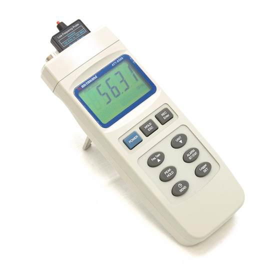
5. FRONT PANEL DESCRIPTION Fig. 1 5-1 Display 5-11 Probe Input Socket 5-2 Power Button 5-12 Probe Memory Card 5-3 Hold / Esc Button 5-13 DC Adapter Input Socket 5-4 REC / Enter Button 5-14 RS-232 Output Terminal 5-5 Freq. Team Select Button 5-15 LCD contrast adj. -
Page 11: Measurement Consideration
6. MEASUREMENT CONSIDERATION 1) According to the measuring object's frequency to select the right probe : EP-03H probe : 100 MHz to 3 GHz. EP-04L probe : 100 kHz to 100 MHz. 2) After select convenient the probe, then plug in the exclusive "... -
Page 12: Measuring Procedure
7. MEASURING PROCEDURE 7 -1 Buttons instructions Buttons Function Power Button Press this key to power on or off. Hold Button Press this key to freeze the reading value. ESC Button When operate " SET " or " Data logger " functions, press this key to escape.. -
Page 13: Symbols & Units Of Display
7 -2 Symbols & units of display Symbol & Function Unit Electric field strength W/m^2 Power density mW/cm^2 Power density 100kHz..Frequency team indicates...3GHz PEAK HOLD Appears on the " PEAK HOLD " function. It will latch the peak value. Appears on the "... -
Page 14: Unit Selection
7-3 Unit Selection After inserting the " Probe card " ( 5-12, Fig. 1 ) and connecting probe's plug into the " Probe Input Socket " ( 5-11, Fig. 1 ), use " Unit Button " ( 5-6, Fig. 1) to select the "... -
Page 15: Alarm Limit Setting And Alarm Start
* Press the " Unit Button " ( 5-6, Fig. 1 ) continuously and > 2 seconds, the bottom display will show X_axis , then release the button, the upper display will show the EMF value of X direction. * Press the " Unit Button " ( 5-6, Fig. 1 ) continuously and >... -
Page 16: Data Hold
7-7 Data hold During the measurement, press the " Hold Button " ( 5-3, Fig. 1 ) once will hold the measured value & the LCD will indicate a " HOLD " symbol. Press the " Hold Button " once again will release the data hold function. -
Page 17: How To Recording Data
7-10-1 How to recording data a) If press the Logger Button " ( 5-10, Fig. 1 ) once will show the sampling time value on the bottom left display then disappeared. b)Press the " REC Button " ( 5-4, Fig. 1 ) once to start the Data Record function and it will be a "... -
Page 18: How To Sending Data
e) Memory full Under execute the data logger, if the bottom right display show the " Full ", it indicate the memory data already over 16,000 no. and the memory is full. f) Stop the Data Logger During the Data Logger function is executed, press the "... - Page 19 LCD display will show the fowling screen alternately. 31.44 ← → Transmit mode xx:xx:xx Transmit mode Block no. The first Start time Start data data of of each address of each block block each block Up Button, Down Button to select the ▲...
- Page 20 Data 1 Block 1 Data X ↓ Data X+1 Block 2 Data Y ↓ ........↓ Data Z Block 250 Data 16,000 * Until the desired Memory Block no. be selected. Press the " Send Button " ( 5-9, Fig. 1 ) once, the data in the Memory Block will send out.
-
Page 21: How To Show Sample Time
Remarks : * If intend up load the data to the computer, then should connect the RS232 cable ( optional, model : UPCB-02) and apply the Data Logger software ( optional, Model : SW-DL2005 ). * When sending the data, each time just can send one Memory Block data out. -
Page 22: Interior Setting Mode
8. INTERIOR SETTING MODE Press the " SET button " ( 5-10, Fig. 1 ) continuously and over two seconds, the display will show : XXXXX Memory space Press " SET button " once again Clear memory ESC:N Enter:Y Press " SET button " once again Date/Time set XX:XX:XX ^,v Enter ( >... -
Page 23: Check Memory Space
8-1 Check Memory Space To check the balance data numbers that exist into the memory ( allow memorize data no. ). XXXXX Memory Space * XXXXX is the balance data numbers, for example XXXXX=15417. 8-2 Clear Memory * To delete the existing save data numbers from the memory. -
Page 24: Sample Time Setting
8-4 Sample Time Setting * Use Up Button, Down Button and Enter ( ▲ ▼ → Button to select the expect Sample Time ( HOUR-MIN. -SEC.). * After finish the Sample Time adjustment, Press the " Enter Button " once , then press the " ESC Button " will quit and save the clock data into the memory. -
Page 25: Rs232 Pc Serial Interface
9. RS232 PC SERIAL INTERFACE The instrument has RS232 PC serial interface via a 3.5 mm terminal ( 5-14, Fig. 1 ). The data output is a 16 digit stream which can be utilized for user's specific application. A RS232 lead with the following connection will be required to link the instrument with the PC serial port. - Page 26 Each digit indicates the following status : End Word = 0D D1 & D8 Display reading, D1 = LSD, D8 = MSD For example : If the display reading is 1234, then D8 to D1 is : 00001234 Decimal Point(DP), position from right to the left 0 = No DP, 1= 1 DP, 2 = 2 DP, 3 = 3 DP Polarity...
-
Page 27: Battery Replacement
10. BATTERY REPLACEMENT When the left corner of LCD display show " ", it is necessary to replace the batteries ( 006P ). 1) Slide the " Battery Cover " ( 5-16, Fig. 1 ) away from the instrument and remove the battery. 2) Replace with batteries ( 006P ) and reinstate the cover.
Need help?
Do you have a question about the ATT-8509 and is the answer not in the manual?
Questions and answers