Table of Contents
Advertisement
Quick Links
Advertisement
Table of Contents

Related Manuals for Aktakom ATA-2504


Summary of Contents for Aktakom ATA-2504
- Page 1 C l a mp Me t e r www.tmatlantic.com...
- Page 2 EN 61010-2-032 CAT II 600V CAT III 300V Pollution Degree 2 SYMBOLS showed on the clamp meter or in this manual: Caution, risk of danger. Refer to accompanying documents Caution, risk of electric shock. Double Insulation Application around and removal from HAZARDOUS LIVE conductors is permitted.
- Page 3 Overvoltage Category I (CAT I): Equipment for connection to circuits in which measures are taken to limit the transient overvoltages to an appropriate low level. Overvoltage Category II (CAT II): Energy-consuming equipment to be supplied from the fixed installation. Overvoltage Category III (CAT III): Equipment in fixed installations.
-
Page 4: Table Of Contents
TABLE OF CONTENTS I.Features …………………………………………………………………………… 3 II. Panel Description ………………………………………………………………. 4 III. Operating Instructions ………………………………………………………… 5 A. DC Current Measurement ………………………………………………….. 5 B. AC Current Measurement ………………………………………………….. 5 C. Current Waveform Observation (Connected to an Oscilloscope) ……….. IV.Specifications ………………………………………………………………….. V. Battery Replacement ………………………………………………………….. VI. -
Page 5: Panel Description
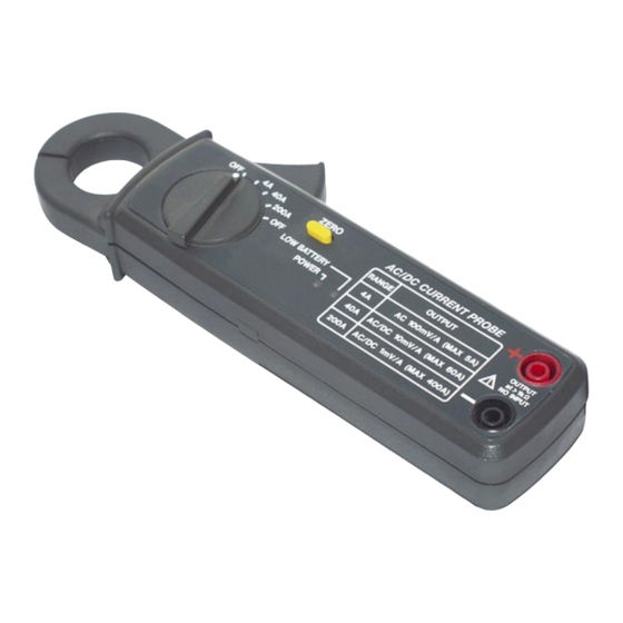
II. Panel Description tactile barrier 1. Transformer Jaw To measure DC/AC current, enclose the conductor by the jaw. 2. Transformer Trigger Push the trigger to open the jaw. 3. Zero Button Push the zero button to zero the output voltage before measuring any current. 4. -
Page 6: Operating Instructions
III. Operating Instructions A. DC Current Measurement 1.Set the rotary switch at 4A, 40A or 200A. 2.Plug one end of each test lead into the meter terminals 3.Plug in the other end of the test lead into a multimeter. 4.Make sure current probe's and multimeter's COM terminals are connected. -
Page 7: Current Waveform Observation (Connected To An Oscilloscope)
3.Plug in the other end of the test lead into a multimeter. It is strongly recommended a TRUE RMS multimeter is used for AC current measurement for more accurate reading. 4.Make sure current probe's and multimeter's COM terminals are connected. 5.Set the range of multimeter at 200 or 400 mVAC for AC current measurement. - Page 8 This unit is not designed to measure DC 0-4A with resolution of DC 1mA. The output voltage will change within 0.4mV. Range Sensitivity DCA 0-4A 0.1mV/1mADC DCA 0-40A 0.1mV/10mA DC DCA 0-200A 0.1mV/100mA DC ACA 0-4A 0.1mV/1mA AC ACA 0-40A 0.1mV/10mA AC ACA 0-200A 0.1mV/100mA AC...
-
Page 9: Battery Replacement
V.Battery Replacement When the low battery LED lights, replace the old batteries with two new batteries. A. Remove the test leads from the current. B. Remove the screw of the battery compartment. C. Lift and remove the battery compartment. D. Remove the old batteries. E.
Need help?
Do you have a question about the ATA-2504 and is the answer not in the manual?
Questions and answers