Table of Contents
Advertisement
Quick Links
Advertisement
Table of Contents

Related Manuals for Aktakom ATE-9051


Summary of Contents for Aktakom ATE-9051
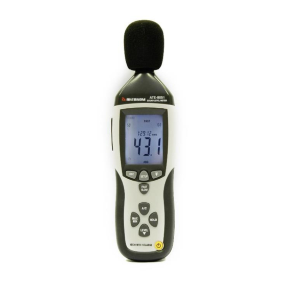
- Page 1 SOUND LEVEL METER ATE-9051 User’s Manual www.tmatlantic.com...
-
Page 2: Safety Information
SAFETY INFORMATION Read the following safety information carefully before attempting to operate or service the meter. Use the meter only as specified in this manual: Environment conditions ① Altitude lower than 2000 meters ② Relatively humidity ≤90%RH ③ Operation Ambient 0 ~ 40℃ Maintenance &... -
Page 3: Specification
This Sound Level Meter is designed for noise project; quality control; illness prevention and cure and all kinds of environmental sounds measurement.It is applied to the sounds measurement at factory; school; office; traffic access and household, etc. This unit confirms to the IEC61672-1 CLASS2 for Sound Level Meters. - Page 4 Med:50dB~100dB Hi:80dB~130dB Auto:30dB~130dB Frequency weighting: Time weighting: FAST ( 125ms ), SLOW ( 1s ) Microphone: inch electret condenser microphone Display: 4 digits LCD display with a resolution of 0.1dB Display Update: 2 times/sec. MAX hold: Hold the Maximum reading MIN hold: Hold the Minimum reading HOLD:...
-
Page 5: Name And Functions
Data output : USB data traffic Auto power off : Meter automatically shuts down after approx. 15 minutes of inactivity. Power supply : One 9V battery, 006P or NEDA1604 or IEC 6F22. Power life : About 30hours Operation temperature and humidity: 0℃~40℃,10%RH~90%RH Storage temperature and temperature: -10℃~+60℃,10%RH~75%RH... - Page 6 FAST ① Windscreen ② LCD:...
- Page 7 SYMBOL FUNCTION 4 digits Maximum hold Minimum hold OVER over range UNDER under range FAST Fast response SLOW Slow response A-Weighting(responseto human sense) C-Weighting(response machine monitor)
- Page 8 88—180 Range indicate Recording data into computer AUTO Auto level range selection FULL Memory full HOLD Data hold function AutopoweroffPress the”SETUP“ button to disable power off Low battery indicate ③REC button 3.0 DATALOGGER function Press “REC” button after it power on, the display will show “REC”...
- Page 9 Press‘SETUP’button and then power it on,when‘TIME’ symbol displays then loosen‘SETUP’ , the meter will be under time adjustment mode,at the time the display will show the date as following: Press the‘SETUP’button second time, the display showing: The display showing “minute” adjustment mode, press ‘LEVEL’...
- Page 10 The display showing “hour” adjustment mode, press ‘LEVEL’ to make the adjustment,press‘HOLD’to keep the setup; Press the‘SETUP’button fourth time, the display showing The display showing “date” adjustment mode, press ‘LEVEL’ to make the adjustment,press‘HOLD’to keep the setup; Press the‘SETUP’button fifth time, the display showing:...
- Page 11 The display showing “month” adjustment mode, press ‘LEVEL’ to make the adjustment,press ‘HOLD’ to keep the setup; Press the‘SETUP’button sixth time, the display showing: The display showing “year” adjustment mode, press ‘LEVEL’ to make the adjustment,press ‘HOLD’to keep the setup; Press the ‘...
- Page 12 The display showing default range, which can’t be adjusted. Press the‘SETUP’button ninth time, the display showing: The display showing initialization of the time chip,time and date have returned to factory setup. When the battery is exhausted or replaced, if the time can’t be adjusted then please initialize the time chip first.
- Page 13 software COM3 ( COM4 ) , then press ‘ SETUP ’, ‘ ’ disappears from the display to indicate and disable auto power off, that the USB data is transmitting. ⑤ FAST/SLOW button: time weighting selection FAST:Fast sampling measurement, 1 time per 125mS. SLOW:Slow sampling measurement, 1 time per second.
-
Page 14: Backlight Button
Each time you press “LEVEL” button, the level range will change between ‘Lo’ level, ‘Med’ level, ‘Hi’ level and ‘Auto’ level in the circular. ⑧ Backlight button Turn the backlight on/off ⑨ Frequency weighting select button A:A-Weighting C:C-Weighting ⑩ HOLD button: Press “HOLD”... - Page 15 For connection with DC 9V power supply. Aperture size: external diameter: 3.5mm, internal diameter: 1.35mm USB interface USB signal output is a 9600 bps serial interface. ⒁ AC/DC signal output earphone outlet OUTPUT OUTPUT GROUND AC:Output voltage: 1Vrms corresponding to each range step.
-
Page 16: Calibration Procedures
For external standard level calibration adjustments. Tripod mounting screw Battery cover Microphone 1/2 inch Electret Condenser microphone 5. CALIBRATION PROCEDURES ①Make the following switch settings: Frequency weighting: A-weighting Time weighting: FAST Level range: 50 ~100dB ②Insert the microphone housing carefully into the 1/2 inch insertion hole of the calibrator (94dB @ 1KHZ). -
Page 17: Measurement Preparation
shipment. Recommended recalibration cycle: 1 year. Acoustic Calibrator FAST 6. MEASUREMENT PREPARATION ① Remove the battery cover on the back and put in one 9V battery. ② Recover the back cover. ③ When battery voltage drops below the operating voltage or battery aging, this symbol will appear on LCD. -
Page 18: Operating Procedure
7. OPERATING PROCEDURE ① Power on the meter. ② Press ‘LEVEL’ button to select desired level, base on ‘UNDER’ or ‘OVER’ do not appear on LCD. ③ Select ‘dBA’ for general noise sound level and ‘dBC’ for measuring sound level of acoustic material. ④... - Page 19 Keep microphone dry and avoid severe vibration. 9. accessories: ① installation CD ② USB interface cable ③ screwdriver ④ tripod ⑤ windscreen ⑥ DC 9V power supply. 10. Installing the software Start windows Insert the CD into the CD-drive. Run SETUP.EXE installation program in file DISK1, install it to the referred directory 1.3 install CP2102 drive software:...
- Page 20 Connecting the meter with the computer by USB interface, install CP2102 drive software in computer property:\hardware\facility management\ COM CP210X USB. USB Drive Installation 1. Copy the CP2101WIN Drivers to a certain directory, such as: C:\ 2. Connect the USB to the computer, the Windows system will show finding a new hardware.
- Page 21 computer. 1.5 Enter the menu REAL TIME\ ‘ SETUP ’ to set the monitoring data(data volume, response, monitoring time) 1.6 DATALOGGER menu: The computer read the memory data in the meter when REC not appear on the display and the connection is in order.
Need help?
Do you have a question about the ATE-9051 and is the answer not in the manual?
Questions and answers