Table of Contents
Advertisement
Quick Links
Advertisement
Table of Contents

Related Manuals for Aktakom ACM-2047


Summary of Contents for Aktakom ACM-2047
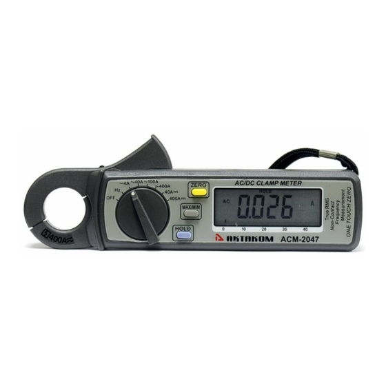
- Page 1 Clamp Meter ACM-2047 USER’S MANUAL www.tmatlantic.com...
- Page 2 EN 61010-2-032 CAT II 600V CAT III 300V Pollution Degree 2 SYMBOLS showed on the clamp meter or in this manual: Caution, risk of danger. Refer to accompanying documents Caution, risk of electric shock. Double Insulation Application around and removal from HAZARDOUS LIVE conductors is permitted.
- Page 3 Overvoltage Category I (CAT I): Equipment for connection to circuits in which measures are taken to limit the transient overvoltages to an appropriate low level. Overvoltage Category II (CAT II): Energy-consuming equipment to be supplied from the fixed installation. Overvoltage Category III (CAT III): Equipment in fixed installations.
-
Page 4: Table Of Contents
TABLE OF CONTENTS I.Features ........................1 II. Panel Description ....................2 III.Operation Instructions ..................4 3.1 DC/AC Current Measurements ..............4 3.2 Frequency (Hz) Measurement ............... 4 3.3 Relative Reading Measurements ..............5 3.4 Holding the LCD Reading ................5 3.5 Finding the MAX/MIN Value ................ -
Page 5: Panel Description
II. Panel Description tactile barrier 1. Transformer Jaw This is used to pick up current signal. To measure DC/AC current, conductor must be enclosed by the jaw. 2. Transformer Trigger This is used to open the jaw. 3. Function Selector Switch This is the on/off switch and used to select the function user desired, such as DCA, ACA, DCV, ACV, Hz, Ohm and Continuity. - Page 6 7. LCD This is a 3 3/4 digit Liquid Crystal Display with maximum indication of 3999. Function symbols, units, bargraph, sign, decimal points, low battery symbols, max/min symbols, and zero symbol are included. 8. Low Battery Symbol When this symbol appears, it means the battery voltage drops below the minimum required voltage.
-
Page 7: Iii.operation Instructions
III.Operation Instructions 3.1 DC/AC Current Measurements 3.1.1 DC Current a. Set the rotary switch at appropriate DC range. b. Push the zero button to adjust the reading to zero. c. Press the trigger to open the jaw and fully enclose the conductor to be measured. -
Page 8: Relative Reading Measurements
i. Set the rotary switch at Hz. j. Press the trigger to open the jaw and fully enclose the conductor to be measured. If line frequency is to be measured, enclose only one line of the line source and make sure there is current flowing. k. -
Page 9: Iv.specifications
IV. Specifications(23 C±5 C) DC Current: Range Resolution Accuracy Overload Protection 10mA ±1.0%±2dgts DC 400A 400A (0-150A) 100mA ±1.0%±2dgts DC 400A 400A (150-200A) 100mA ±2.2%±2dgts DC 400A 400A (200-400A) 100mA ±4.0%±2dgts DC 400A AC Current (True RMS, Crest Factor <= 4): Overload Accuracy Protection... - Page 10 Operating Humidity: less than 85% relative Storage Temperature: -20 C to 60 C Storage Humidity: less than 75% relative Altitude up to 2000M Dimension: 183mm(L)x61.3mm (W) x 35.6mm (H) 7.2" (L) x 2.5" (W) x 1.4" (H) Weight: 190g (battery included) Accessories: Carrying bag x 1...
-
Page 11: V.battery Replacement
V.Battery Replacement When the low battery symbol is displayed on the LCD, replace the old batteries with two new batteries. A. Turn the power off and remove the test leads from the clamp meter. B. Remove the screw of the battery compartment. C.
Need help?
Do you have a question about the ACM-2047 and is the answer not in the manual?
Questions and answers