Table of Contents
Advertisement
Quick Links
Download this manual
See also:
Instruction Manual
Advertisement
Table of Contents

Related Manuals for Kirisun FM540


Summary of Contents for Kirisun FM540
- Page 1 FM540 Service Manual FM540...
-
Page 2: Table Of Contents
FM540 Service Manual Contents 1. Overview ..............................1 1.1. Scope ..................................1 1.2. Safety Precaution ..............................1 2. External Views and Key Features ......................2 2.1 Front Panel ................................2 2.2 LCD Display ................................3 2.3 Rear Panel................................4 2.4 Microphone (Handheld) ............................4 3. - Page 3 Appendix 3 Material Specification(Electronical Parts 400-470) .............. 55 Appendix 4 Material Specification (Stucture) .................... 74 Figure 1 FM540-01Mainboard Schematic Diagram(136-174MHz) ............79 Figure 2 FM540-01 Top Layer Position Diagram(136-174MHz) ............. 86 Figure 3 FM540-01Bottom Layer Position Diagram(136-174MHz) ............87 Figure 4 FM540-02 Mainboard Schematic Diagram(400-470MHz) ............88 Figure 5 FM540-02 Mainboard Top Layer Position Diagram 400-470MHz ........
-
Page 4: Overview
1. Overview 1.1. Scope This manual is intended for the maintenance & repair of FM540 and used by engineers and professional technicians trained by Kirisun. Dada changes in this manual may occur with the improvement of technology. To get the latest technology information, please contact us or your local distributors. -
Page 5: External Views And Key Features
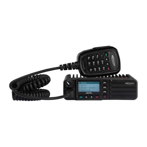
FM540 Service Manual 2. External Views and Key Features 2.1 Front Panel Part Name Part Name Volume Control Knob Microphone/Programming Port Rotate the knob toadjust the volume LCD Display P1 Key (programmable key) Refer to “LCD Display” section LED Indicator Red indicator glows: transmitting. -
Page 6: Lcd Display
FM540 Service Manual 2.2 LCD Display Icon Description Signal strength indicator. The signal gets stronger with more signal bars. Unread Message Full Inbox The current channel is scanning High Power Low Power Analog Channel Digital Channel Emergency state (except secret alarm) or an emergency alarm is received. -
Page 7: Rear Panel
FM540 Service Manual 2.3 Rear Panel Part Name Part Name Antenna Port Power Port External Speaker Port 2.4 Microphone (Handheld) Part Name PTT Key Press the key to transmit and release to receive. Page 4 of 99... - Page 8 FM540 Service Manual * Key Enter “*”. # Key Switch input method. Enter Key Programmable key. Set as menu navigation enter key by default. Up key Programmable key. Set as Up Key by default. Down Key Programmable key. Set as Down Key by default.
-
Page 9: Circuit Description
FM540 Service Manual 3. Circuit Description 3.1 Overview This is a FM device. 3.2 Frequency Composition of Circuit Figure 3-1 Circuit Schematic 450KHz MIXER IF SYSTEM ANT SW 51.65MHz 12.8MHz TCXO multiply CODEC The receiver applies secondary mixing technology.The first intermediate frequency is 51.65MHz and the second one is 450 kHz. -
Page 10: Rx Principle
FM540 Service Manual 3.3 RX Principle Figure 3-2 RX Schematic MIXER 1st local D3 D37 D36 RF AMP ANT SW PC/TV IC19 TCXO Multiply XF700 IF AMP 51.65MHz AF PA CODEC IF DET 450K • Front End of Receiver The signal received will passTx-Rx switch controller andalso the BPF composed of LC of two levels... -
Page 11: Tx Principle
FM540 Service Manual signal (51.65MHz) in IC6 to generate the second IF signal (450kHz). The second IF signal will be amplified and limited in IC700 and after being filtered by CF1 crystal filter (450kHz), it will be demodulated by IC700 and audio signal will be output. -
Page 12: Principle Of Frequency Synthesizer
FM540 Service Manual 3.5 Principle of Frequency Synthesizer Figure 3-4Diagram of Frequency Synthesizer RX VCO IC12 RF AMP BUFF AMP ½ FREQ PLL IC DATA DATA TX VCO Q25,U2 12.8MHz TCXO This radio applies PLL frequency synthesizer.The frequency synthesizer consists of reference oscillator, voltage controlled oscillator (VCO), programmable frequency divider, phase comparator and low pass filter. -
Page 13: Audio Processing Circuit
FM540 Service Manual 3.6 Audio Processing Circuit Figure 3-5 Frequency Synthesis Diagram Host MCU SCT3252 FM receiver Voice Protocol coder 4FSK stack FM modulator • MIC Signal Processing The audio signal from MIC is sent to U6 for A/D audio switch and sent to U1 SCT3252 for internal adio encoding/decoding, communication protocol processing, channel coding modulation. -
Page 14: Mcu Unit
FM540 Service Manual IC1: 5C switch. 5V circuit is controlled by MCU. 5C supplies power for frequency synthesizer. IC8, IC102: 3V and 1.2V DC\DC voltage stabilizing circuit; supplies DC current for U1 (SCT3252F). IC9: 8V three-terminal voltage stabilizing circuit. 3.8 MCU Unit... - Page 15 FM540 Service Manual 39 groups of standard CTCSS frequency of this radio are available. See Chart 1. CTCSS signal is generated by MCU (PWM wave form), and it is sent to VCO for modulation after being filtered by the low pass filter composed of RC for eliminating the frequency higher than 300Hz.
-
Page 16: Semiconductor Description
FM540 Service Manual 3.9 Semiconductor Description Chart 3-3 Microprocessor (M30620) Port Description Pin No. Port Name Input/ output Function VCCN D/A Output Reference frequency adjustment output TONE_OUT D/A Output DTMF/Tone output, beep output HSDI Tone decoding input EPDT EEPROM data input/ output... - Page 17 FM540 Service Manual XOUT CPU clock output CPU clock input PTT key S_CS FLASH data output S_SO FLASHdata output S_SCK FLASH data output PC/TV TX power,receving frequency band voltage tunning S_SI FLASH data output TXD1 output RXD1 input C_CLK Emulator interface...
- Page 18 FM540 Service Manual RX SW Receiver VCO switch TX SW Transmitter VCO switch C_CE Emulator interface PLL UL Phase-locked loop loss of lock check pin PLL STD Phase-locked loop enabling control PLL DATA Phase-locked loop data output PLL CLK Phase-locked loop clock...
- Page 19 FM540 Service Manual HPI_DATA0 HPI address bus HPI_DATA1 HPI address bus HPI_DATA2 HPI address bus HPI_DATA3 HPI address bus HPI_DATA4 HPI address bus HPI_DATA5 HPI address bus HPI_DATA6 HPI address bus HPI_DATA7 HPI address bus SI/D7 LCD data output SCL/D6...
- Page 20 FM540 Service Manual RSSI Receiving filed intensity signal input BUSY Squelch voltage check input VOL_DET VOL_DET AVSS TEMP TX temperature detection VREF AVCC W/N switch pin Speaker micdata input pin TGSW TX control pin Chart 3-4 Semiconductor Description Position Mark...
- Page 21 FM540 Service Manual UMC4 TX VCO control switch 2SC5108 Feedback loop amplifier DTA143TE RX VCO control switch 2SC4617 VCO power filter 2SC5108 VCO buffer amplifier 2SC5108 RX second local oscillation amplifier 2SC3356 TX VCO oscillation tube 2SC3357 Trasmitter power amplification boost...
-
Page 22: Feature Description And Parameter Settings
FM540 Service Manual D1,D4 1SV305 TX VCO oscillation varactor D5,D6 D14,D15D16,D 1SV305 RX VCO oscillation varactor HSC277 RX VCO output switch diode HSC277 TX VCO output switch diode HZU5ALL APC output voltage-limiting diode D3,D37 HVC131 Transmitter antenna switch diode D27,D28,D29,D... -
Page 23: Scan Revert Channel
FM540 Service Manual 4.2.2. Scan Revert Channel When the radio is scanning, press the PTT button” and the radio transmits and communicates on a preset channel. This channel can be programmed by the local distributor. 4.3 Kill and Unkill If the dealer enables this feature, the radio can receive and decode other radio’s signals of Kill and Unkill before responding accordingly. -
Page 24: Feature And Parameter Settings
The stepsof setting parameters with computer are as below: Step 1.Install FM540 programming software on the computer. Step 2. Use FM540 programming cable to connect the radio to PC serial port. See the following: Note: please turn off the radio before connection. -
Page 25: Assembling And Disassembling
FM540 Service Manual 5. Assembling and Disassembling This radio is sophisticated communication equipment with a precise and compact mechanism. The assembly and disassembly of the radio must be carefully performed during the repair. The description is as follows: 5.1 Exploded View Part No. - Page 26 FM540 Service Manual 7MHJ-4090-01A-W FM540 lens double-sided adhesive 7SMF-025050M-MHYB-B M2.5*5 flat round torx-head machine screw 7MBP-4090-03A-WC FM540 light pipe 7PLJ-4028-E02A KME-221 brand sticker 7MBP-4090-01A-W0 FM540 front shell 7MHR-1939-03A-W0 PT8000 speaker dust-proof net 4SS7-3520-016-700 Speaker 3WPT-S1938-01A Black and white twisted pair...
-
Page 27: Maintenance And Disassembling Description
7MHS-4090-01A-J FM540 metal dome key 6SS2-4090-HKA FM540 keyboard suite 7MHS-4090-02A-W FM540 key PCB grounding spring 7STF-026060B-SZYB-Z Screw M2.6*6 5.2 Maintenance and Disassembling Description 5.2.1. RF-PCB Disassembling Description Step 1. Unscrew the six M3*25 screws on the top and bottom cover,as shown in ,open the aluminum bottomcover ( see the figure below). - Page 28 FM540 Service Manual PCB(see the figure below). Step 3. Loose the four M2.5*5 panel screws as shown in . Disassemble the metal panel,plastic buckleand speaker plug (see the picture below). Step 4.Unplug the flat cable and speaker cable, and use the soldering iron to separate the antenna head from RF-PCB;...
-
Page 29: Key-Pcb Disassembling Description
FM540 Service Manual 5.2.2. Key-PCB Disassembling Description Step 1. loose the six 6 M3*25 screws on the top and bottom cover as shown in , and open the aluminum bottom cover (see the figure shown below). Step 2. remove the flat cable and speaker cable from the mainboard as shown in Step 3. -
Page 30: Test And Modulation
FM540 Service Manual plastic panel.(seethe figure shown below). After the disassembly, you can perform further repair and modulation based on faults. 6. Test and Modulation 6.1 Test and Modulation Method During the repair, changing components may require proper test and modulation according to the technical specifications of the radio. -
Page 31: Modulation By Computer
FM540 Service Manual 6.1.3. Modulation by Computer 1.TX frequency On the computer mode [frequency stability], the transmitting frequency is adjusted within ±100Hz. 2.Power a.On the computer mode [TX high power], adjust the TX high power as 25W±2W. b.On the computer mode [TX middle power], adjust the power middle power as 10W±2W. -
Page 32: Radio Test
FM540 Service Manual 3. First Level Squelch Adjustment a.Set the RF signal as -122dBm, modulated frequency deviation as 1.5kHz. On the computer mode(open), click OK when the value is stable. b.Set the RF signal as -124dBm, modulated frequency deviation as 1.5kHz. On the computer mode (close), click OK when the value is stable. -
Page 33: Major Technical Performance And Specifications
FM540 Service Manual 7. Major Technical Performance and Specifications 7.1 General Specifications Product Model FM540 Frequency Range UHF: 400-470MHz VHF: 136-174MHz 4FSK/11KФF3E Modulation Method Channel Capacity Channel Spacing 12.5kHz Intermediate Frequency IF: 51.65MHz, 2 IF: 450kHz Working Voltage 13.8V negative pole grounding... -
Page 34: Tx Specification
FM540 Service Manual 7.3 TX Specification TX Power 25W/10W/5W @13.8 DC ≤ ±2.5ppm Frequency Stability Maximum Modulated Frequency ±2.5kHz Deviation ≤ 3% Modulated Distortion 300~3000Hz ≥60dB Adjacent Channel TX Power ≥70 dB Spurious Transmission ≥40 dB Residual Modulation ≤8A @ 13.8 DC... -
Page 35: Service And Test Equipment
FM540 Service Manual 8. Service and Test Equipment During service and modulation, please use the device listed below: Device Major Specification Frequency Range: 0 - 1GHz Standard Signal Generator Modulation: frequency modulation and external modulation Output: from 127dBm/0.1uv to 47dBm/1mv... - Page 36 FM540 Service Manual A Poor contact of antenna. Re-fix the antenna. B Low sensitivity. Adjust the “test mode”. C High-frequency amplification tube Q703 failed. Change to a new tube. Failed to receive D The squelch level is too high so the squelch cannot be turned on.
-
Page 37: Appendix 1 Acronyms
FM540 Service Manual Appendix 1 Acronyms amplify, amplifier antenna automatic power control band pass filter CTCSS continuous tone control squelch system Digital code squelch Demodulation DEMOD E2PROM Electrically erasable programmable read-only memory high pass filter instantaneous deviation control intermediate frequency... -
Page 38: Appendix2 Material List Electrics136-174Mhz
FM540Service Manul Appendix2 Material List Electrics136-174MHz Material No. Material Name Specification Quantity Position No FM540-01 Radio 136-174MHZ,6.25KHZ 136-174MHZ 6SS2-4092-HMB FM540-01Mainboard Suit mobile,6.25KHZ FM540-01 Mainboard Plug-In 0SS2-4092-HMA 136-174MHZ,6.25KHZ Material 5FT3-CFWLB450KJ Ceramic filter CFWLB450KJFA-B0,450kHz FA-B0 ±2kHz,murata,leadfree 5FT3-LTM450FW-A R Ceramic filter LTM450FW,450KHZ±7KHZ frequency detector... - Page 39 FM540-01patch material suit mobile,6.25KHZ, FM540-01Mainboard patch 136-174MHZ 0SS1-4092-HMD material mobile,6.25KHZ, FM540V-20150911.PCB:93.5 6PM7-4092-BMD FM540-01 mainboard PCB X141mm thickness:1.6MM,4 FM540-01v Band Mainboard PCB layers,FR-4,leadfree EMI,FILTER, 5FE1-BLM41P600S R Chip EMI suppression filter SMT,BLM41P600SPT,1206,l L25,L26 eadfree 1IS1-GT3136 E patch special IC GT3136,SSOP16 Wire Diameter:φ0.9,Inner...
- Page 40 FM540Service Manul Wire Diameter :φ0.9,Inner 2LH1-R903R0-L06- R chip Air Core Inductor Diameter:φ3.0,6Circles,Legs L18,L28 Height:0.5mm,Back Roll Chip Memory: IC Replaced 1IM1-AT24C512C AT24C512C,leadfree IC200 By:1IM1-AT24C512BN 2CC1-10-X5R6R3-1 R Chip Multilayer Capacitor 1005,1uF±10%,6.3V,X5R C296,C449,C450,C56,C120,C254 2CC1-10-C0G500-1 R Chip Multilayer Capacitor 1005,10P±0.5P,50V,C0G C7,C138,C139 C127 2CC1-10-Y5V160-1 1005,1uF+80%/-20%,16V,Y5 Chip Multilayer Capacitor C11,C386 2CC1-10-C0G500-1...
- Page 41 FM540Service Manul 2CC1-10-C0G500-3 R Chip Multilayer Capacitor 1005,3P±0.25P,50V,C0G C413,C175,C80 2CC1-32-C0G102-1 R Chip Multilayer Capacitor 3216,15P±5%,1000V,C0G 2CC1-32-C0G102-3 R Chip Multilayer Capacitor 3216,30P±5%,1000V,C0G 2CC1-32-C0G102-2 R Chip Multilayer Capacitor 3216,22P±5%,1000V,C0G C94,C152 2CC1-32-C0G102-1 R Chip Multilayer Capacitor 3216,10P±5%,1000V,C0G C417 2CC1-10-X7R500-1 C133,C81,C110,C115,C121,C153,C33,C51, C330, R Chip Multilayer Capacitor 1005,10nF±10%,50V,X7R C333,C55,C385,C170,C171 2CC1-32-C0G102-1...
- Page 42 FM540Service Manul 2CC1-32-C0G102-1 R Chip Multilayer Capacitor 3216,18P±5%,1000V,C0G C408 2CC1-32-C0G102-3 R Chip Multilayer Capacitor 3216,3P±0.25P,1000V,C0G Chip: Temperature DSA221SJ,12.2880MHz,±1.5 5OD1-12R28-ACL-2 Compensated Crystal PPm,-40 +85 Oscillator(TCXO) ,2.5*2.0*0.8mm C3,C12,C20,C54,C68,C71,C76,C87,C116,C119,C 136, C148,C151,C157,C160,C169,C174,C178, 2CC1-10-X7R500-4 C182,C207,C212,C215,C218,C221,C222, R Chip Multilayer Capacitor 1005,470P±10%,50V,X7R C274,C283,C332,C339,C340, C342,C343,C347,C392,C395,C348,C9,C158,C23 6,C240,C242,C244,C263, C420,C421 2CC1-16-X7R500-1 C64,C67,C78,C79,C84,C85,C86, R Chip Multilayer Capacitor 1608,1000P±10%,50V,X7R...
- Page 43 FM540Service Manul 2CC1-10-C0G500-3 Chip Multilayer Capacitor 1005,330P±5%,50V,C0G C140 2CC1-10-C0G500-6 R Chip Multilayer Capacitor 1005,68P±5%,50V,C0G C132 2CC1-10-C0G500-4 R Chip Multilayer Capacitor 1005,47P±5%,50V,C0G C129 2CC1-10-C0G500-6 R Chip Multilayer Capacitor 1005,6P±0.25P,50V,C0G C73,C72,C161,C164,C177,C166 2CC1-10-C0G500-4 R Chip Multilayer Capacitor 1005,4P±0.25P,50V,C0G C35,C163,C208,C201,C162 2CC1-10-C0G500-9 Chip Multilayer Capacitor 1005,9P±0.25P,50V,C0G C100 C48,C44,C65,C173,C183,C184,C186,C187,C102,...
- Page 44 FM540Service Manul 2CC1-10-X7R250-2 R Chip Multilayer Capacitor 1005,22nF±10%,25V,X7R C239,C238 2CC1-10-X7R100-3 R Chip Multilayer Capacitor 1005,39nF±10%,10V,X7R C250,C251 2CC1-10-X7R250-1 R Chip Multilayer Capacitor 1005,12nF±10%,25V,X7R C292,C388 2CC1-10-C0G500-8 Chip Multilayer Capacitor 1005,8P±0.25P,50V,C0G C192,C165 2CC1-10-C0G500-2 R Chip Multilayer Capacitor 1005,27P±5%,50V,C0G C194,C197,C198 2CC1-10-C0G500-3 R Chip Multilayer Capacitor 1005,3.5P±0.25P,50V,C0G C180 2CC1-10-C0G500-2...
- Page 45 FM540Service Manul 2CC1-10-X7R160-4 R Chip Multilayer Capacitor 1005,47nF±10%,16V,X7R C287 1608,0Ω 2RS1-16-000O R Chip Resistance C30,C75,C31,C176,L52,L62,R12,L13 2CC1-10-C0G500-3 R Chip Multilayer Capacitor 1005,36P±5%,50V,C0G C205 2CC1-10-C0G500-3 R Chip Multilayer Capacitor 1005,39P±5%,50V,C0G C225,C229 2CC1-10-X7R500-1 R Chip Multilayer Capacitor 1005,15nF±10%,50V,X7R C389,C387 2CC1-10-X7R500-1 Chip Multilayer Capacitor 1005,18nF±10%,50V,X7R C390,C391 2CC1-10-C0G500-1...
- Page 46 FM540Service Manul Dual 1DS1-DAN222 R Chip switching diode Diode:DAN222(TL),SOT23(R D20,D21 OHM) 1DZ1-HZU5ALL R chip voltage-regulator diode HZU5ALL,2012,5V 1DZ1-02DZ18-X R chip voltage-regulator diode Vmin=16.80V,Vmax=17.76V 1IS1-XC6204B502 Voltage Regulator Integrated R chip Voltage Regulator IC IC11 5V,SOT-23-5 D1,D4,D5,D6,D14,D16,D17,D18 1DV1-1SV305 R chipVariode 1SV305 D27,D28,D29,D30 1DV1-1SV278 R chipVariode 1SV278(T1)
- Page 47 FM540Service Manul 2CE1-VS250-470M R chip aluminum electrolytic 6.3×5.3,47μF±20%,25V C66,C373,C341 0605 capacitor 3216,4.7μF±20%,16V,TS 2CT1-TS32-160-4R R chip tantalum capacitor Series(A Leve) 2CC1-20-Y5V160-1 2012,10uF+80%/-20%,16V,Y Chip Multilayer Capacitor C452,C453,C454,C456,C457,C458,C455 2CC1-20-Y5V100-3 2012,330nF+80%/-20%,10V, R Chip Multilayer Capacitor C181 2CC1-20-X7R6R3-4 2012,4.7uF±10%,6.3V,X7R( R Chip Multilayer Capacitor C154,C237,C241,C257,C258 GRM219R6J475KE19D) 3FW1-1206L150PR R chip fuse 1206L150PR,1206,1.5A/6V...
- Page 48 FM540Service Manul 2520,0.47μH±10%,Ceramics 2LW1-25UC-471K R Chip Wire-wound Inductance Chip(FLM2520-R47K) 2520,820nH±10%,Ceramic 2LW1-25UC-821K R Chip Wire-wound Inductance Chip(FLM2520-R82K) 1608,56nH±5%,Ceramic 2LW1-16UC-560J R Chip Wire-wound Inductance Chip(C1608CB-56NJ) L1,L4,L23,L24,L32,L33,L39, 1608,BLM11A601S/BLM18A 5FE1-BLM11A601S R EMIsuppression filter L59,L60,L61,L63,L65,L69,L76,L78,L67,L71,L73,L8 G601S(0138-05) 0,L81,L203 2RS1-20-470J R Chip Resistance 2012,47Ω±5% 2012,22Ω±5% 2RS1-20-220J R Chip Resistance 2012,BLM21P300S/BLM21P 5FE1-BLM21P300S R chip EMIsuppression filter...
- Page 49 R Chip Wire-wound Inductance Chip(C2012C-56NJ) 2012,0Ω 2RS1-20-000O R Chip Resistance 2012,47nH±2%, Ceramic 2LW1-20UC-470GA R Chip Wire-wound Inductance Chip(C2012C-47NG) 5FE1-BLM11A221S 1608,BLM11A221SPT/BLM1 R chip EMIsuppression filter FB7,FB8,FB9 8AG221S(0138-05) 5FE1-BLM18EG221 Chip EMIsuppression filter BLM18EG221SN1,0603 FB16,FB17 CPU,M16C-M3062LFGPGP,f 1IP1-0FM540-R01 FM540 programming IC IC19 reelead Page 46 of 99...
- Page 50 FM540Service Manul Need upgradeCPU, 1IP1-M16CM3062L E R chip CPU M16C-M3062LFGPGP,FLAS FGPGP 9FSO-FM540R114 FM540 MCU software FM540_R114 25Q32BVSSIG,8PIN,SOIC ,l 1IM1-25X32VSIG Chip Sliced Memeory IC eadfree Chip switching 1DS1-L8104 diode(replacable by L8104,Litec,leadfree D3,D11,D36,D37 1DS1-L709CE 1IS1-MB15E03SL E R chipPLL IC MB15E03SL,TSSOP-16 1TF1-3SK318 R chipDual-Gate MOSFET...
- Page 51 FM540Service Manul 1TT1-2SC5108-Y R chip triode 2SC5108-Y(MC),NPN Q1,Q2,Q20,Q11 R chip triode replacable by 1TT1-2SC3357 2SC3357(RE),SOT89(NEC) 1TT1-2SC4988 1TT1-2SC4617-R R chip triode 2SC4617-R(BR),EMT3 Q14,Q51,Q52,Q21 1TT1-KTA1298-Y R chip triode KTA1298-Y,SOT23 Q38,Q40 chip triodereplacable by 1TT1-2SA1834 2SA1834(-20V, -10A) 1TT1-2SA1641-S 1IS1-PST9124NR R chipresetIC ResetIC,PST9124NR IC202 2RS1-10-222J R Chip Resistance 1005,2.2K±5%...
- Page 52 FM540Service Manul 1005,560Ω±5% 2RS1-10-561J R Chip Resistance 2RS1-10-272J R Chip Resistance 1005,2.7K±5% R17,R214 R324,R65 2RS1-10-104J R Chip Resistance 1005,100K±5% R60,R67,R80,R40,R59,R52,R53,R203,R360 C319,R38,C43 C29,R172,R164,R174,R72,R145,R66 R320,R84,R85,R86,R301,C134,C135,R182,R188, 1005,0Ω 2RS1-10-000O R Chip Resistance R206,R230,R253,R266,R269, R322,R323,C246,C248,R161,R150,C249,R153,C 253,R155,C52,C53,R27 2RS1-10-823J R Chip Resistance 1005,82K±5% R75 C451 2RS1-10-182J R Chip Resistance 1005,1.8K±5% 1005,680Ω±5% 2RS1-10-681J...
- Page 53 FM540Service Manul 2RS1-10-274J R Chip Resistance 1005,270K±5% R36,R42,R302,R316,R318 2RS1-10-273J R Chip Resistance 1005,27K±5% R118,R64 1005,68Ω±5% 2RS1-10-680J R Chip Resistance 2RS1-16-103J R Chip Resistance 1608,10K±5% 1005,100Ω±5% 2RS1-10-101J R Chip Resistance R121,R26 2RS1-10-563J R Chip Resistance 1005,56K±5% R125,R97,R160 R162,R127,R129,R141,R105,R123,R89,R126, 2RS1-10-473J R Chip Resistance 1005,47K±5% R321,R363,R364,R365,R370,R371,R372 2RS1-10-105J...
- Page 54 FM540Service Manul 2RS1-10-682J R Chip Resistance 1005,6.8K±5% R113,R94,R95,R314,R114 2RS1-10-392J R Chip Resistance 1005,3.9K±5% R152,R178 2RS1-10-332J R Chip Resistance 1005,3.3K±5% R142,R197,R124,R146,R183 1608,10Ω±5% 2RS1-16-100J R Chip Resistance R8,R30 1608,560Ω±5% 2RS1-16-561J R Chip Resistance R23,R22 2RS1-10-334J R Chip Resistance 1005,330K±5% R108,R134,R339 2RS1-10-153J R Chip Resistance 1005,15K±5% R56,R366 1005,470Ω±5%...
- Page 55 FM540Service Manul 2RS1-10-393J R Chip Resistance 1005,39K±5% R143,R631 2RS1-10-224J R Chip Resistance 1005,220K±5% R310 2RS1-10-564J R Chip Resistance 1005,560K±5% R99,R73 1608,680Ω±5% 2RS1-16-681J R Chip Resistance 2RS1-10-394J R Chip Resistance 1005,390K±5% R308 2RS1-10-562J R Chip Resistance 1005,5.6K±5% R361,R175 2RS1-10-512J R Chip Resistance 1005,5.1K±5% R179,R200,R219 2RS1-10-822J...
- Page 56 Chip Temperature 12.8MHz±1.5ppm,Vcont=1.5 5OT1-12R8-ACL4-0 Compensated Crystal V±1.0V Range:±20ppm,-40 Oscillator Frequency 1IS1-UPB1509GV R chip Specialized IC IC12 Detector:UPB1509GV,SSOP CODEC Chip FP520 FM540 WM8758CB, 32-Pin QPN 1IS1-WM8758B Specialized Material Package5*5*0.9MM,leadfree 1IS1-XC6204B332 Voltage Regulator Integrated Chip Voltage RegulatorIC IC8, 3.3V,SOT-23-5,150mA Power Supply 1IS1-XC6228D122V...
- Page 57 Transistors Spacing:0.5mm,34 3CF1-BL112-34RL R chipFPC/FPC Connector Core,BL112-34RL,Horizontal Low Contact With Lock 1005,10P±5%,50V,C0G, 2CC1-10-C0G500-1 Chip Multilayer GJM1555C1H100JB01, C62 C63 CapacitorDR650-1 FM540-1 HIQ(High Q Value) 0603,22pF±5%,High Q,High 2CC1-16-C0G250-2 Chip Multilayer Capacitor Power ,Ceramics Capacitor,250V 3216,0.33μF±20%,35V,TS 2CT1-TS32-350-R3 R chip tantalum capacitor C113 Series(A Level)
-
Page 58: Appendix 3 Material Specification(Electronical Parts 400-470)
Chip Wire-wound Inductance Core,(HWI0805UC27NG) 2CC1-10-C0G500-3 Chip Multilayer Capacitor 1005,3P±0.1P,50V,C0G C106 Appendix 3 Material Specification(Electronical Parts 400-470) Material No. Material Name Specification Quantity Note FM540-02 Main 400-470MHZ,6.25KHZ Machine FM540-02 DPMR Digital Mobile FM540-02 Mobile 6SS2-4090-BMB Radio,400-470MHz,25W Radio Page 55 of 99... - Page 59 E R Plug In Three Terminal Voltage 1IS3-L7808CV VotageRegulator IC Regulator:L7808CV(8V),TO220 E R Audio Amplifier 1IS3-TDA1519C TDA1519C,SIL9,Plug In Socket,PHType,Spacing2mm,2 3CL3-PH-20002 R Stripe Connector cores/WCPW20-02 FM540-02 Mobile FM540-02Moile Radio Mainboard chip 6SS1-4090-BMB Radio Mainboard chip kits Kits Page 56 of 99...
- Page 60 FM540Service Manul FM540-02 Mobile FM540-02 Mobile Radio chip 0SS1-4090-BMC Radio Mainboard Material,400-470MHz. Chip Material FM540-02U Band 20150602.PCB FM540-02 Mobile 6PM7-4090-BMB SIZE:93.5X141mm 1.6MM 4 Layers FM540-01v Radio PCB FR-4 leadfree 5FE1-BLM41P600S EMI,FILTER, chipEMIsuppression L25,L26 SMT,BLM41P600SPT,1206,leadfree filter 1IS1-GT3136 E chip Specialized IC GT3136,SSOP16 Wire Diameter:φ0.9,Inner...
- Page 61 FM540Service Manul 2CC1-10-X5R6R3-1 R Chip Multilayer 1005,1uF±10%,6.3V,X5R C296,C449,C450,C56,C120,C254,C123 Capacitor 2CC1-10-C0G500-1 R Chip Multilayer 1005,10P±0.5P,50V,C0G C80,C7,C138,C139,C62,C63,C53,C197 Capacitor 2CC1-10-Y5V160-1 Chip Multilayer 1005,1uF+80%/-20%,16V,Y5V C11,C386 Capacitor 2CC1-10-C0G500-1 R Chip Multilayer 1005,12P±5%,50V,C0G C194,C198 Capacitor 2CC1-10-C0G500-1 R Chip Multilayer 1005,13P±5%,50V,C0G Capacitor 2CC1-10-C0G500-1 R Chip Multilayer 1005,18P±5%,50V,C0G C732 Capacitor 2CC1-10-X7R500-1...
- Page 62 FM540Service Manul 2CC1-32-C0G102-4 R Chip Multilayer 3216,4P±0.25P,1000V,C0G Capacitor 2CC1-10-X7R500-1 R Chip Multilayer C133,C121,C153,C33,C330, 1005,10nF±10%,50V,X7R Capacitor C333,C385,C170,C171,C102,C82,C98 2CC1-32-C0G102-1 R Chip Multilayer 3216,1000P±5%,1000V,C0G Capacitor 2CC1-32-C0G102-5 R Chip Multilayer 3216,5P±5%,1000V,C0G C128 Capacitor 2CC1-32-C0G102-7 R Chip Multilayer 3216,7P±0.25P,1000V,C0G C407,C45 Capacitor 2CC1-32-C0G102-3 R Chip Multilayer 3216,3P±0.25P,1000V,C0G C419,C15 Capacitor...
- Page 63 FM540Service Manul C60,C61,C21,C167,C188,C189,C196,C206,C214, 2CC1-10-X7R500-1 R Chip Multilayer 1005,1000P±10%,50V,X7R C220,C223,C230,C231,C49,C89,C57,C370,C58,C Capacitor 59,C427,C428,C122,C39,C191 2CC1-10-C0G500-1 R Chip Multilayer 1005,1P±0.25P,50V,C0G C69,C70,C177 Capacitor 2CC1-16-C0G500-2 R Chip Multilayer 1608,2P±0.25P,50V,C0G Capacitor 2CC1-16-C0G500-1 R Chip Multilayer 1608,10P±0.5P,50V,C0G C107,C124,C22 Capacitor 2CC1-10-C0G500- R Chip Multilayer 1005,0.5P±0.1P,50V,C0G C409,C406,C398,C4 R50B Capacitor 2CC1-10-X7R250-1 Chip Multilayer 1005,10nF±10%,25V,X7R C145...
- Page 64 FM540Service Manul Capacitor C48,C44,C65,C173,C183,C184,C186,C187, C209,C210,C211,C213,C235,C259, C264,C268,C271,C325,C17, 2CC1-10-X7R160-1 R Chip Multilayer C329,C83,C334,C337,C338,C172, 1005,100nF±10%,16V,X7R Capacitor C394,C260,C262,C272, C275,C281,C300,C302,C315,C377 C436,C437,C438,C439,C440,C441 C461,C462,C463,C464,C144,C190,C96,C81,C115 C105,C108,C112,C103,C114, C349,C350,C351,C354 C356, 2CC1-10-C0G500-1 R Chip Multilayer C359,C360,C361,C362,C363, 1005,100P±5%,50V,C0G Capacitor C378,C379,C380,C381,C382,C383,C384,C125,C 36,C37,C99,C90,C91 2CC1-10-C0G500-8 R Chip Multilayer 1005,82P±5%,50V,C0G C234 Capacitor 2CC1-10-X7R250-2 R Chip Multilayer 1005,22nF±10%,25V,X7R C239,C238 Capacitor...
- Page 65 FM540Service Manul 2CC1-10-X7R500-3 Chip Multilayer 1005,33nF±10%,25V,X7R,Replaced C429,C430 Capacitor By 2CC1-10-X7R250-333K 2CC1-16-C0G500-1 R Chip Multilayer 1608,100P±5%,50V,C0G C18,C111 Capacitor 2CC1-16-C0G500-6 R Chip Multilayer 1608,6P±0.25P ,50V,C0G Capacitor 2CC1-16-C0G500-5 R Chip Multilayer 1608,56P±5%,50V,C0G Capacitor 2CC1-16-C0G500- R Chip Multilayer 1608,0.5P±0.1P,50V,C0G R50B Capacitor 2CC1-10-C0G500-5 R Chip Multilayer 1005,5P±0.25P,50V,C0G Capacitor 2CC1-10-C0G500-3...
- Page 66 FM540Service Manul Capacitor 2CC1-10-X7R500-1 R Chip Multilayer 1005,15nF±10%,50V,X7R C389,C387 Capacitor 2CC1-10-X7R500-1 Chip Multilayer 1005,18nF±10%,50V,X7R C390,C391 Capacitor 2CC1-10-C0G500-1 R Chip Multilayer 1005,150P±5%,50V,C0G C195,C204,C76,C71,C68 Capacitor Diode 1SS381,On Resistance0.6 1DS1-1SS381 Swicher Diode D2,D19 Ohms Revert Capacitor 1.2PF 30V 1DG1-DSM3MA1 R Chip diode SM3MA1 R Chip switching 1DS1-DA2S10100L DA2S10100L...
- Page 67 FM540Service Manul 1IS1-XC6204B502 R chip Voltage Voltage RegulatorIntegrated IC11 RegulatorIC 5V,SOT-23-5 D1,D4,D5,D6,D14,D16,D17,D18,D23, 1DV1-1SV305 R chipVariode 1SV305 D24,D26,D27,D28,D29,D30 1DV1-1SV278 R chipVariode 1SV278(T1) 2012,2.2μF±20%,10V,TP Series (P 2CT1-TP20-100-2R R chip tantalum C233 capacitor Level) 3216,1μF±20%,16V,TS Series(A 2CT1-TS32-160-1R R chip tantalum C117 capacitor Level) 2012,4.7μF±20%,10V,TP Series(P 2CT1-TP20-100-4R R chip tantalum...
- Page 68 FM540Service Manul 2CC1-20-Y5V100-3 R Chip Multilayer 2012,330nF+80%/-20%,10V,Y5V C181 Capacitor 2CC1-20-X7R6R3-4 R Chip Multilayer 2012,4.7uF±10%,6.3V,X7R(GRM219R C154,C237,C241,C257,C258 Capacitor 6J475KE19D) R chip Insurance 3FW1-1206L150PR 1206L150PR,1206,1.5A/6V Fuse 1IS1-HT9172 E R Chip DecoderIC DTMF Decoder IC,HT9172,18SOP 1TT1-2SC3356-R24 R chip triode 2SC3356-R24,SOT23,NPN Q6,Q12 Chip Wire-wound 1608,330nH±2%(C1608BR33G),leadfr 2LW1-16UC-R33G L5,L37,L51,L21,L68,L27 Inductance...
- Page 69 FM540Service Manul chipEMIsuppression 149-05) filter 1608,0.22μH±5%(LG HK 2LL1-16-R22J R multilayer inductor 1608R22J-T/MLG1608B220N) 1608,1μH±10%(MLF1608A1R0K) 2LL1-16-1R0K R multilayer inductor 2LL1-16-R56K R multilayer inductor 1608,560nH±10%(MLF1608DR56K) 1608,0.47μH±10%(MLF1608DR47K) 2LL1-16-R47K R multilayer inductor R Chip Wire-wound 1608,15nH±5%, Ceramic 2LW1-16UC-150J L20,L16, L17 Inductance Core(C1608CB-15NJ) 2LL1-16-18NJ R multilayer inductor 1608,18nH±5%(MLG1608B18NJ) L45,L46 Chip Wire-wound...
- Page 70 ChipEMI Suppression BLM18EG221SN1,0603 FB16,FB17 filter FM540Programmable 1IP1-0FM540-R01 CPU,M16C-M3062LFGPGP,leadfree IC19 Chip 1IP1-M16CM3062L Blank Chip should programming,CPU, E R chipCPU FGPGP M16C-M3062LFGPGP,FLASH FM540 MCU 9FSO-FM540R114 FM540_R114 Software 1IM1-25X32VSIG Chip MemoryIC 25Q32BVSSIG,8PIN,SOIC,leadfree Chip switching 1DS1-L8104 diode(Replaced By L8104,Litec,leadfree D3,D11,D36,D37 1DS1-L709CE 1IS1-MB15E03SL E R ChipPLL IC...
- Page 71 FM540Service Manul 1TT1-2SC5108-Y R chip triode 2SC5108-Y(MC),NPN Q1,Q2,Q20,Q11 R chip triode 1TT1-2SC3357 Replaced By 2SC3357(RE),SOT89(NEC) Q5,Q4 1TT1-2SC4988 1TT1-2SC4617-R R chip triode 2SC4617-R(BR),EMT3 Q14,Q51,Q52,Q21 1TT1-KTA1298-Y R chip triode KTA1298-Y,SOT23 Q38,Q40 chip triode Replaced 1TT1-2SA1834 2SA1834(-20V, -10A) By1TT1-2SA1641-S 1IS1-PST9124NR R chipresetIC resetIC,PST9124NR IC202 2RS1-10-222J R Chip Resistance...
- Page 72 FM540Service Manul R27,C52,C319,C43,C29,R172,R164,R174,R72,R1 45,R66 R320,R84,R85,R86,R301,C134,C135,R182,R188, 1005,0Ω 2RS1-10-000O R Chip Resistance R206,R230,R253,R266,R269, R322,R323,C246,C248,R161,R150,C249,R153,C 253,R155,R38,C93,R260 2RS1-10-823J R Chip Resistance 1005,82K±5% R75,C451 2RS1-10-122J R Chip Resistance 1005,1.2K±5% R196,R205,R81,R35,R79,R24,R112,R15,R233,R2 59,R258, 2RS1-10-103J R Chip Resistance 1005,10K±5% R280,R10,R284,R285,R305,R306,R307,R309,R31 1,R313,R76,R344,R345,R346,R362, R374,R375,R377,R378,R257 2RS1-10-154J R Chip Resistance 1005,150K±5% R6,R166,R167,R218,R226,R11,R123 R383,R369 ,R368,R376 ,R109,R110,R194,R106,R 2RS1-10-223J R Chip Resistance...
- Page 73 FM540Service Manul R321,R363,R364,R365,R370,R371,R372,R67 R87,R137,R139,R130,R131,R133,R312,R185,R2 2RS1-10-105J R Chip Resistance 1005,1M±5% 0,R62 R282,R170,R171,R70,R201,R48,R83,R315,R136, 2RS1-10-102J R Chip Resistance 1005,1K±5% R337,R292,R144,R176,R180,R340,R379 2RS1-10-184J R Chip Resistance 1005,180K±5% R177,R92,R117 1005,150Ω±5% 2RS1-10-151J R Chip Resistance R111,R63 2RS1-10-474J R Chip Resistance 1005,470K±5% R140,R303,R317,R319 2RS1-10-152J R Chip Resistance 1005,1.5K±5% R211,R57 2RS1-10-682J R Chip Resistance...
- Page 74 FM540Service Manul 1005,56Ω±5% 2RS1-10-560J R Chip Resistance R115,R135 1608,120Ω±5% 2RS1-16-121J R Chip Resistance R61,R41 1005,120Ω±5% 2RS1-10-121J R Chip Resistance 1005,22Ω±5% 2RS1-10-220J R Chip Resistance R33,R103 2RS1-10-333J R Chip Resistance 1005,33K±5% R156,R157,R151,R359, 2RS1-10-393J R Chip Resistance 1005,39K±5% R631 2RS1-10-224J R Chip Resistance 1005,220K±5% R310 2RS1-10-564J...
- Page 75 FM540Service Manul B104K Digital Baseband 1IS1-SCT3252PS SCT3252PS LQFP100 leadfree Processing Chip 1IS1-SCT3252PN Baseband Chip SCT3252PN Baseband Chip 1IM1-ST24 Vocoder 6.25K Series Vocoder/ST24 6.25K Series 1ID1-MC74VHC1G MC74VHC1GT04 SC-88A/SOT353 Single Reverser IC leadfree Chip Temperature 5OT1-12R8-ACL4-0 12.8MHz±1.5ppm,Vcont=1.5V±1.0V Compensated Range:±20ppm,-40 Oscillator WM8758CB, 32-Pin QPN 1IS1-WM8758B CODEC Chip Package :5*5*0.9MM,leadfree...
- Page 76 FM540Service Manul E R Chip Crystal 5XT1-3R58-A 3.58MHz,SMT-49,30PPM Oscillator 5XC1-9R8-MPL20-0 R Chip Crystal 9.8304MHz±30PPM,±50PPM,16P,-40 X200 Oscillator to+80 ,NX5032GA 1TT1-DTA144EE R chip triode Digital Triode DTA144EE-SMD Q23,Q36 1TF1-SSM3K15AF R chip Field Effect SSM3K15AFS D1 Q704,Q8,Q25 Transistor Spacing:0.5mm,34 R chipFPC/FPC 3CF1-BL112-34RL Cores,BL112-34RL,Horizontal Low Connector Contact With Lock 1608,8.2nH±0.5nH(MLG1608B8N2DT...
-
Page 77: Appendix 4 Material Specification (Stucture)
Chip Wire-wound 1608,27nH±2%,Ceramic Core 2LW1-16UC-270G Inductance (C1608CB-27NG) Appendix 4 Material Specification (Stucture) Material No. Material Name Specification Unit Quantity FM540 Main Unit Assembling 0SS3-4092-HMA Module 1317 Material SL16-50KF-03 Copper Plating,Plug And Unplug 3CR7-S1943-B R Antenna Head Force :1-2.5KGF,leadfree Square Copper Core... - Page 78 Material :ABS,Black,leadfree 3FG7-6030-313010 R Fuse Glass Type,φ6*30mm,32V,10A 7MBP-7038-03A-W R Power Cable Latch Material:ABS,Black,leadfree 7MBR-4090-01A-W FM540 Silcon Gel Button Material:SilconGel,Transparent,leadfree 7MHR-1939-04A-W R Panel Up Sealed Slice Material:Flocking,Single Sided With Odhesive,black,leadfree 7MHR-1939-04A-W R Panel Down Sealed Slice Material:Flocking,Single Sided With Odhesive,black,lleadfree 7MHR-1939-04A-W...
- Page 79 FM540 LCD Module Black and white screen ZYWF151,leadfree 7GCM-603810-01A- R Shock Protective Sponge Black Soft Sponge,60*38*10 Cushion 7MBP-4090-08A-W FM540 Functional Key P1 Mold Trasparent Cold Grey Oil Printed Laser Carving leadfree 7MBP-4090-09A-W FM540 Functional KeyP2 Transparent Cold Grey, Oil Printed Laser Carving,leadfree...
- Page 80 7MHS-4090-02A-W FM540 LCD Bracket SUS304 48 hours Salt-Fog Testing Original Color leadfree 6SS3-MK4090-BMA FM540 Cover Assembly FM540 Cover Assembly 7MBP-4090-03A-W FM540 Light Guide Tube Mold PC,Transparent,leadfree 7MBP-4090-01A-W FM540 Plastic Panel PC365,Black,Texture,leadfree 7MBP-4090-04A-W FM540 Menu Key Mold 1 Transparent Red Oil Printed Lazer Carving leadfree...
- Page 81 FM540Service Manul FM540 Key Board Assembly 6SS2-4092-HKA Suit Φ3mm,Two Color(Red and Green),GHZRG603D2-2C(Con-Positive) 4PE3-3R0-Y25-A R Plug In Lighting Diode 3CT3-PCB-8HKB R Plug In Hand Mic Socket RJ45 8P Full Plastic,leadfree 2RW3-R09542NO-F Potentiometer R Volume R09542NO-FB12.5A07-A103-015 B12.5 Page 78 of 99...
-
Page 82: Figure 1 Fm540-01Mainboard Schematic Diagram(136-174Mhz)
FM540Service Manul Figure 1 FM540-01Mainboard Schematic Diagram(136-174MHz) TA78033AF IC2 C342 C343 IC11XC6204B332MR C263 C237 C240 4.7uF/6.3V L7808CV IC9 C331 C329 C330 C332 C333 C334 F1 1.5A Q39 2SA1641 470uF/25V KTA1298 KTA1298 R281 BLM21P300S BLM21P300S C337 C338 C340 10D220 R284 R285 10K... - Page 83 FM540Service Manul R366 R367 R383 R382 R340 C429 C430 R372 C30922P 33nF 33nF R371 R370 C344 R341 R369 C413 R368 Q204 L203 BLM11A601S INT0 S_SCK PLLBYPASS VC_12.288M PLLSEL2 S_SO HCSN S_CS HWRN ENC_3 HRDN ENC_2 HOBIB ENC_1 RSTN_3252 ENC_0 IC202 BLM11A601S EXT_PTT R365...
- Page 84 FM540Service Manul HOLE_7 HOLE_7 HOLE_7 VDDIO33 HOLE_7 HOLE_7 HOLE_7 Hole Hole Hole VDDIO33 Hole Hole Hole VDDIO33 VDDIO33 R164 VDDIO33 TRSTN VDDIO33 R182 VDDIO33 R188 VDDIO33 R323 0R VDDIO33 HOLDA SCT3252MOD VDDIO33 VDDIO33 PIO0 SCL_CODEC VDDIO33 PIO1 SDA_CODEC R206 VDDIO33 PIO2/VSS HOLE_7 HOLE_7...
- Page 85 FM540Service Manul IC12 UPB1509GV UPB1509GV R183 C279 3.3K 2.2uF VCC1 VCC2 R184 C280 FIRST_LOCAL C65 8.2K C13 102 BLM11A601S 2SC5108 150P 330nH 100R 2.2K 4.7K 820nH 1SV305 2SC5108 82nH 330nH C3 471 BLM11A601S 4.7uF/10V 39nH R169 C282 2SC3356 150K 1SV305 C17 104 100R UNLOCK:0V...
- Page 86 FM540Service Manul RA30H1317M C418 C419 HSC277 C30 0R R380R C26 102 100P 100P L709CE FIRST_LOCAL C36 102 C398 C417 C407 C408 C409 TO ANT 560R 0.5P 0.5P C324 2.2K 68nH C51 103 C410 C406 560R 0.5P 0.5P HZU5ALL 47uF/25V 47uF/25V C372 MA742 C84 102...
- Page 87 FM540Service Manul RSSI 47nH 33nH C161 C162 D19 HSC277 FIRST_LOCAL C165 W:H N:L 4.7K C166 RF_RX DTA144EE R280 BUSY DTA144EE R337 W:L N:H W:H N:L C167 180K 150nH 450KHz HT 6.8K 6.8K XF700 51.65MHZ R100 R101 DTC144EE DAN222 C169 DAN222 R102 560K C170 330R...
- Page 88 FM540Service Manul R106 C184 C183 2T_DET TDA1519C R116 R128 IC5 HT9172 R126 BLM11A601S R162 R127 C215 C211 C216 RT/GT R134 4.7K 4.7uF/10V 2SK1824 C259 330K VREF C265 R105 TONE_OUT C225 10uF PWDN R194 R139 C268 C269 R151 R196 10K C271 AOUT1L C229 R201 1K...
-
Page 89: Figure 2 Fm540-01 Top Layer Position Diagram(136-174Mhz)
FM540Service Manul Figure 2 FM540-01 Top Layer Position Diagram(136-174MHz) Page 86 of 99... -
Page 90: Figure 3 Fm540-01Bottom Layer Position Diagram(136-174Mhz)
FM540Service Manul Figure 3 FM540-01Bottom Layer Position Diagram(136-174MHz) Page 87 of 99... -
Page 91: Figure 4 Fm540-02 Mainboard Schematic Diagram(400-470Mhz)
FM540Service Manul Figure 4 FM540-02 Mainboard Schematic Diagram(400-470MHz) TA78033AF 4.7uF/6. 2 47 3 47 IC11 XC6204B332MR 3 47 0 4 7 7 4.7uF/6. L7808CV F11. 9 A 1 0 1 0 1 4 70uF/ 2 V 4 8 KTA12 3 1 0... - Page 92 FM540Service Manul RX_S AFCO_ C_CL C_BUS 6 1 5K 7 2 2K Y C_EP NC_C SCT3252MO 0 1 K 9 33nF 0 33nF C309 GREEN_LE D RED_LE SHIF 3 3 P 1 1 0R L203 4 NC BLM11A601 9.8304 I S _SC S_SCK PLLBYPAS VC_12.288M...
- Page 93 FM540Service Manul HOLE_7 HOLE_7 HOLE_7 VDDIO33 HOLE_7 HOLE_7 HOLE_7 Hole Hole Hole VDDIO33 Hole Hole Hole VDDIO33 VDDIO33 R164 VDDIO33 TRSTN VDDIO33 R182 VDDIO33 R188 VDDIO33 R323 0R VDDIO33 HOLDA SCT3252MOD VDDIO33 VDDIO33 PIO0 SCL_CODEC VDDIO33 PIO1 SDA_CODEC R206 VDDIO33 PIO2/VSS HOLE_7 HOLE_7...
- Page 94 FM540Service Manul R183 3.3K C280 C7 10P R184 FIRST_LOCAL 8.2K 150P BLM11A601S 330nH 100R 2SC5108 2.2K 4.7K 1SV305 330nH 2SC5108 33nH 330nH C3 471 BLM11A601S 4.7uF/10V 220R 0.5P 150K 330R 5.6K 1SV305 2SC3356 C17 104 UNLOCK:0V R10 10K R11 150K C33 103 120R C35 3P...
- Page 95 FM540Service Manul IC1 RA30H4047M C419 R38 0R C26 102 C27 22P C28 22P L709CE 1SS381 C30 0R C31 6P 2SC3357 FIRST_LOCAL C36 100P C37 100P L709CE C409 TO ANT C324 C407 C417 0.5P C408 C128 430R 7P C46 8.2nH 8.2nH C398 4.7K 15nH...
- Page 96 FM540Service Manul RSSI 18nH 18nH HSC277 C161 C162 FIRST_LOCAL C165 C164 C163 W:H N:L C166 4.7K RF_RX DTA144EE R280 BUSY W:L N:H W:H N:L R337 C167 DTA144EE 180K 68nH 450KHz HT 6.8K 6.8K XF700 0.33uH MA2S111 R100 51.65MHZ R101 DTC144EE C171 DAN222 DAN222...
- Page 97 FM540Service Manul R106 C184 C183 2T_DET TDA1519C R116 IC5 HT9172 R126 BLM11A601S R162 R127 C211 C215 C216 RT/GT R134 C210 4.7K SSM3K15AFS 4.7uF/10V 330K C259 VREF R105 C265 TONE_OUT C225 10uF PWDN R194 R139 C268 C269 C271 R151 R196 10K AOUT1L C229 R201 1K...
-
Page 98: Figure 5 Fm540-02 Mainboard Top Layer Position Diagram 400-470Mhz
FM540Service Manul Figure 5 FM540-02 Mainboard Top Layer Position Diagram (400-470MHz) Page 95 of 99... -
Page 99: Figure 6 Fm540-02 Mainboard Bottom Layer Position Diagram 400-470Mhz
FM540Service Manul Figure 6 FM540-02 Mainboard Bottom Layer Position Diagram (400-470MHz) Page 96 of 99... -
Page 100: Figure 7 Fm540 Key Board Schematic Diagram
FM540Service Manul Figure 7 FM540 KEY Board Schematic Diagram HOLE_7 HOLE_7 3.3K Hole Hole SW13 SW14 SW15 SW16 ON/OFF RJ45 HOOK 3.3K DOWN CANCEL FM540_LCD_CON 0R L2 C117 4.7uF/6.3V T600 SI/D7 SCL/D6 HOLE_7 HOLE_7 Hole Hole /RST /CS1 4.7uF/6.3V 4.7uF/6.3V... -
Page 101: Figure 8 Fm540Keytop Layer Position Diagram
FM540Service Manul Figure 8 FM540KEYTop Layer Position Diagram Page 98 of 99... -
Page 102: Figure 9 Fm540Key Bottom Layer Position Diagram
FM540Service Manul Figure 9 FM540KEY Bottom Layer Position Diagram Page 99 of 99...
Need help?
Do you have a question about the FM540 and is the answer not in the manual?
Questions and answers