Table of Contents
Advertisement
Quick Links
Advertisement
Table of Contents

Related Manuals for Kirisun FP420


Summary of Contents for Kirisun FP420
-
Page 2: Table Of Contents
Appendix 3 Spare Parts List (Structure Part) ............... 39 Appendix 4 Accessories reference List ................ 41 Figure1 FP420 Schematic Pane Diagram ..............42 Figure2 FP420 Top Board Position Mark Diagram ............48 Figure3 FP420 Bottom Board Position Mark Diagram..........49 Page 1 of 50... -
Page 3: Chapter 1 Overview
Chapter 1 Overview 1.1 Introduction This manual applies to the service and maintenance of FP420 FM portable radios, and is intended for use by engineers and professional technicians that have been trained by Kirisun. It contains all the required service information for the equipment. Kirisun reserves the right to modify the product structure and specifications without notice in order to enhance product performance and quality. -
Page 4: Chapter 2 External View And Functional Keys
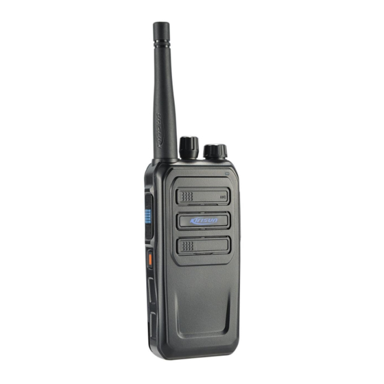
FP420 Service Manual * Replacement Parts All components used for repair should be supplied by Kirisun. Components of the same type available on the market are not surely able to be used in this product and we do not guarantee the quality of the product using such components 1.3 Service... - Page 5 FP420 Service Manual Figure 2.1 ○ Antenna ○ Press the key and talk to make a call; release the key to listen ○ PF Button The button can be assigned different functions through PC software by your dealer. Details refer to the following “Programmable Key” in this instruction.
- Page 6 FP420 Service Manual Moniter: If the current analog channel is with CTCSS/CDCSS, press the key to squelch mode to cancel the CTCSS/CDCSS function. Press the key again to return to the original status. Emergency alarm open: Start the Emergency Alarm function to seek help.
-
Page 7: Chapter3 Circuit Description
FP420 Service Manual speak to the MIC. On an analog channel, press the PTT Button and speak to the MIC. Receiving a call When receiving the signal, the signal strength will be indicated on LCD. While on digital channels, when receiving private call/group call/all call, the radio will output the voice. - Page 8 FP420 Service Manual RDA1846 LT1801A POWER AFAMP Figure 3.3 Principle of Receiver Receiver is mainly used in receiving, selecting, amplifying, transforming, demodulating etc. and other processing like audio signal amplifying, filtering. Audio part mainly is used to post emphasis, amplify and filter audio signal.
- Page 9 FP420 Service Manual Audio power amplifier U600 and peripheral components makes up the audio power amplifier circuit Q601 base is the control end. High level: U2 begins to make audio; Low level: closed. Receive audio signals, voice signals, alarm sound signals are summarized and sent to speaker through audio power amplifier.
- Page 10 FP420 Service Manual represents the stability of the transmitter also. Output is 0.8W, G about 12db. Q500 Q501 grid bias is controlled by APC circuit. Change the gate bias voltage, can easily control the size of the transmitter output power.
- Page 11 FP420 Service Manual 5T: supply power for front-end transmitter 5 R: supply power for receiver RF amplifier, audio signal processing unit etc. IC102:3C switch controlled by MCU, Provide 3.3 V 3C: receive 3V electricity controlled by power save, supply power for RDA1846S.
- Page 12 FP420 Service Manual 3.6.6. Ultra low power sleep mode 3.6.7. Three line serial digital interface control 3.7 semiconductor devices MCU instructions Table 3.7 the microprocessor (LT1801A) port Port function Name SIRIN SECRET_IO(Reserved for Encryption chip) SIROUT POW_C(Soft switch on power control)...
- Page 13 FP420 Service Manual LCDCRD LCD_RD LCDCRS LCD_RS LCDCWR LCD_WR LCDCS0 LCD_CS LCDCS1 LCD_RST LCDC0 LCD_D0 LCDC1 LCD_D1 LCDC2 LCD_D2 SCLK1 SPEAKER_POP/AGC_PD(AGC enable chip) SSN1 SRX1 STX1 RX_SW MOTO_EN 或 LAMP(Keypad light) PWM0 PWM1 LCD_BACK GPO0 P_UL(Indicate frequency lock state) GPO1 5T(TX power control)...
- Page 14 FP420 Service Manual BUSY RFIF Simulation of DAC VCCN(TCXO reference voltage) ( AUXDA module input voltage ) range of 1.15-2.15 V RFIF Simulation of DAC TV/PC ( AUXDA module voltage input ) range is 0 to 3 v RX_I+ Simulation of the...
- Page 15 FP420 Service Manual amplitude=1.53V after closed MIC input MIC1(headphone MIC input) input amplitude=96mv when 24dB open; input amplitude=1.53V after closed RXD0 (for GPS) TXD0 (for GPS) RTS0 (for GPS) CTSO (for GPS) GPIO0_12 Hard boot detection RDA1846S port AVDD Power supply...
- Page 16 FP420 Service Manual No connection No connection AVDD Power supply PABIAS PA bias supply for PA AVDD Power supply Chip enable, high active; Chip sleep, low active Gpio7/vox(When Gpio7=V , vox is active; else V GPIO7 GPIO6 Gpio6 / sq (When Gpio6=V , sq is active;...
-
Page 17: Chapter 4 Function Description And Parameter Settings
FP420 Service Manual Q205 DTC144EE MIC Switch Q501 2SC5108 TX 1 amplifier Q503 2SC3356 TX 2st amplifier Chapter 4 Function Description and Parameter Settings 4.1TOT This function forbids you from occupying the channel for a long time. If the continuous transmitting time exceeds the setting time by dealer, the radio sends out a warning tone and stops transmitting. - Page 18 CPSc to set parameters on the radio. The programming steps are as following: Install the programming software of FP420 B. Connect the radio to the computer serial port with the specified programming cable,see figure4.5...
-
Page 19: Chapter5 Disassembly For Repair
FP420 Service Manual Computer(RS232 or USB) Specifiled programming Radio(Speaker/MIC cable socket) Figure4.5 C.Turn on the radio power D.Click the CPSc to run the programming software. E.Click read to read the data from radio. G.About more details, please refer to help file or programming instrunction manual. - Page 20 FP420 Service Manual Notice: Do not short-circuit the battery terminals or dispose of batteries in fire. Do not attempt to disassemble the case of the battery. 5.2 Installing/Removing the Antenna Installing: Hold the base of the antenna and turn the antenna clockwise into the connector on the top of the radio until it’s tightened.
- Page 21 FP420 Service Manual Installing an optional headset When you use an external headset, to open outward headphones cover in the upper right of the radio, plug the external headphone cable into the headset port. 5.4 Removing the Back Cabinet from the Chassis (1) Remove the antenna;...
- Page 22 FP420 Service Manual 5.5 Removing the PCB Board from the Chassis (1) Screw off screws on the main board (2) Take down the waterproof cushion in top and use the soldering iron to cut off the antenna connecting point, and then separate the main board (include PTT PCB) from the aluminium alloy chassis.
- Page 23 FP420 Service Manual After the demolition of the above, you can make the appropriate repairs and debugging against fault conditions. 5.6 Exploded view Page 22 of 50...
- Page 24 FP420 Service Manual Unit Part Code Part Name Specifications 7MHP-4038-06A-W0 FP420 TPU; Black; texture Headphone cover 7MJS-4038-01A-W0 FP420 spindle SUS304;nature color, BaYang, Non-lead 7MHP-4038-01A-W0 FP420 Surface PC+ABS; Black; texture shell 7MHB-7069-01A-W0 PT7800 DY-E002A Breathable film,φ6.6xφ4.4, Microphones waterproof pad 7GCB-S4002-01A 4700 Speaker No anti-cloth;...
- Page 25 FP420 Service Manual cover 7PLJ-4038-E01A S760 Transparent PC Trademark stickers 7MHR-4038-01A-W0 FP420 Side Silica gel; black; Laser carving; silicone key PT Orange21C; 7NRC-060090035-W FP420 Coding Brass, diameter M6mm, OD φ9mm, thick 3.5mm, black nickel plated 7NRC-090115025-G1 3208 nut Brass, diameter M9mm, OD φ11.5mm, 2.5mm thick...
- Page 26 FP420 Service Manual 7MHP-4038-04A-W0 FP420 Coding ABS; Black; texture, white-oil knob 3CR7-SMA-50JF-4 coaxial SMA-J, Flange mounting,used connectors for 7200 7MDZ-1737-04A-J5 KB-58L sticker Dark green paper,8*35mm,thick 0.2mm, single Side with plastic 6BPM-784043-07415 Li-poly battery Li-poly battery pack 78mm* pack (FP420) 40mm*4.3mm×2,7.4V,1500mAh...
-
Page 27: Chapter 6 Adjustment
FP420 Service Manual treatment 7MDP-4057-02A-W0 KB-460 Battery PC+ABS; Black; texture, case back 7MHR-4038-02A-W0 FP420 main Silica gel; black; high gloss Waterproof gasket 7MHR-4038-05A-W0 FP420 Silica gel; black; polishing Bomb-pin socket 7MHL-4038-01A-W FP420 ADC12; Aluminum 7MHP-4038-07A-W0 FP420 TPU; Black; texture, Headphone... -
Page 28: Chapter7 Major Specification
FP420 Service Manual The Tx frequency is the standard frequency ± 100Hz. Frequency (136-174) MHz (400-470)MHz B. Power a. High Power is 3.5-5.0W. b. Low Power is 0.5-1.5W. C. Voltage Voltage is 6.5V. Rx Part A. Max Volume Set RF of the comprehensive tester to be the center frequency, the single strength to be 1mV and the modulation deviation to be 3.0kHz/1.5kHz (wide/narrow band), and... -
Page 29: Chapter 8 Service And Test Equipment
FP420 Service Manual Model FP420 Number of Control Channel 16 Zones x 16 Channels Channel spacing 25kHz/12.5kHz Operating voltage 7.4V, cathode grounded Operating temperature -25° C ~ +55° C 50 Ω Antenna impedance 2.2 Ω Microphone impedance Battery (Standard) Li-ion Battery: DC 7.4V, 1500mAh, Operating time: 12.5h (5: 5: 90 cycle) -
Page 30: Chapter 9 Troubleshooting
FP420 Service Manual During the servicing and test process, the following equipments and apparatus will be used: Equipments Specifications Standard signal Frequency range: 400-470MHz generator Modulation: FM and external modulation Output: -127dBm/0.1 uV to >-47dBm/1mV Output impedance: 50 Ω Power meter... - Page 31 FP420 Service Manual No. Problems Causes and solutions Power ON failure A. The battery pack may be out of power. Please charge it or change a new one B. Power switch in failure. Change a new one. C.MCU in failure. Change the IC.
-
Page 32: Appendix1 Abbreviation
FP420 Service Manual abnormal. Please check the computer. C. The earphone jack of the radio is in poor contact. Please check the earphone jack. If it is abnormal, please change it. Appendix1 Abbreviation amplify, amplifier antenna automatic power control band pass filter... - Page 33 FP420 Service Manual 3CF1-BL112-30RU FFC/FPC connector 0.5mm spacing,30 Pin, horizontal J201 type 1DP1-BV08C R protected diode BV08C D600,D601 1DR1-NSR1020MW2T1 Surface mounting NSR1020MW2T1G, No Pb D101,D102 schttky diode 1DS1-DA2S10100L Surface mounting DA2S10100L D505 switch diode 1DS1-HSC277 Surface mounting HSC277,1608 D502 switch diode (production...
- Page 34 FP420 Service Manual 1TT1-2SC3356-R24 Surface mounting 2SC3356-R24,SOT23,NPN Q503 triode 1TT1-2SC5108-Y Surface mounting 2SC5108-Y(MC),NPN Q502 triode 1TT1-DTA144EE Surface mounting Digital triode, DTA144EE-SMD Q504 triode 1TT1-DTC144EE Surface mounting Digital triode, Q1,Q101,Q103,Q200,Q201, triode DTC144EE(26),SOT323 Q505,Q601,Q604,Q606 1TT1-FMMT717TA Surface mounting FMMT717A,PNP,SOT23 Q600 triode 1TT1-KTA1298-Y Surface...
- Page 35 FP420 Service Manual 2CC1-10-X7R500-103K flake multilayer 1005,10nF±10%,50V,X7R C110,C112,C115,C126,C308 capacitor ,C529,C539,C540,C548,C60 0,C612 2CC1-10-X7R500-471K flake multilayer 1005,470P±10%,50V,X7R C1,C29,C34,C40,C42,C44,C capacitor 46,C48,C50,C52,C102,C104, C113,C118,C122,C128,C130 ,C201,C202,C203,C204,C20 6,C207,C208,C209,C210,C2 11,C213,C214,C215,C217,C 218,C221,C222,C230,C231, C232,C233,C234,C326,C332 ,C519,C522,C523,C526,C52 7,C528,C530,C531,C532,C5 33,C535,C537,C 2CC1-16-C0G500-120J flake multilayer 1608,12P±5%,50V,C0G C507 capacitor 2CC1-16-C0G500-1R0C flake multilayer 1608,1P±0.25P,50V,C0G C534 capacitor 2CC1-16-C0G500-1R5C...
- Page 36 FP420 Service Manual C216,C227,C582,C602,C606 ,C615,C119,C129 3528,47μF±20%,10V,TS 2CT1-TS35-100-470M Surface mounting C605 Tantalum capacitor Series(Grade B) Wire diameter: φ0.40, Inner 2LH1-R401R5-R03-05 R Surface mounting Air L500,L501,L503,L505 diameter: φ1.5, 3 circles, Pin Coil hight: 0.5mm, clockwise circling Wire diameter: φ0.40, Inner 2LH1-R401R5-R04-05 R Surface mounting Air L502 diameter: φ1.5, 4 circles, Pin...
- Page 37 FP420 Service Manual 2RE1-16-1503 Surface mounting 1608,150K±1% R517,R518,R519,R524,R525 exact Resistor ,R527,R528 1005,0Ω 2RS1-10-000O R Chip Resistor R3,R4,R5,R6,R17,R19,R26, R31,R32,C577,R251,R252,R 109,R306,R312,R339,R404, R504,R516,R555,R624,C19, C25,C569,C570,C607 1005,10Ω±5% 2RS1-10-100J R Chip Resistor R2,R244,R300,R559 1005,100Ω±5% 2RS1-10-101J R Chip Resistor R317,R318,R319,R320,R321 ,R322 2RS1-10-102J R Chip Resistor 1005,1K±5% R8,R9,R108,R209,R210,R21...
- Page 38 FP420 Service Manual 2RS1-10-392J R Chip Resistor 1005,3.9K±5% R514 2RS1-10-393J R Chip Resistor 1005,39K±5% R512 1005,47Ω±5% 2RS1-10-470J R Chip Resistor R500 1005,470Ω±5% 2RS1-10-471J R Chip Resistor R15,R612 2RS1-10-472J R Chip Resistor 1005,4.7K±5% R561,R562 2RS1-10-473J R Chip Resistor 1005,47K±5% R202,R203,R204,R205,R206 ,R207,R208,R227,R240,R24...
- Page 39 FP420 Service Manual 0mm,97X21MM, no Pb Chip multi-layer 2CC1-10-X7R500-183K 1005,18nF±10%,50V,X7R capacitor 2RS1-10-683J R Chip resistor 1005,68K±5% 0SS2-4038-HMB S760-02 mainboard plug-in parts (Version D PCB) 7MIC-4038-01A-WC S760_3.5 Earphone Material:T=0.6 PC; transparency; J600 spacer one side glue; no Pb 3CE3-CZ25-C 2.5mm Earphone...
-
Page 40: Appendix 3 Spare Parts List (Structure Part)
FP420 Service Manual Appendix 3 Spare Parts List (Structure Part) 0SS3-4039-HMB FP420 FP420 mainframe assemble ,Lead mainframe free assemble (PCB D Version) 7MHP-4038-02A-W0 S760 top cover Material :PC+ABS; black;texturing;Guokai; Lead free 7MHP-4038-03A-W0 S760 Volume Material:ABS;black;texturing,white oil Knob painted;Guokai;Lead free 7MHP-4038-04A-W0... - Page 41 Clip torsional spring 7MJS-7154-02A-W0 GD-9 Belt Clip SUS304, passed 48H salt spray test, Spindle Lead free 6SS3-MK4039-HMA FP420 front FP420 front case assemble, Lead case assemble free 7MHP-4039-01A-W0 FP420(FP420) Material:PC+ABS;Black;texturning/sil front case e printed;Guokai; Lead free 7MHP-4038-05C-W0 S760PTT cover Material:ABS,double color texturing;0608, Guokai;...
-
Page 42: Appendix 4 Accessories Reference List
FP420 Service Manual 7MHP-4038-06A-W0 S760 Earphone Material:TPU;black; texturing;Guokai; cover Lead free 7MHR-4038-01A-W0 S760 Silica gel Material:silica gel, black, Laser side key Carving Orange21C;Mingkun;Lead free 7MHR-4039-01A-WC FP420(FP420) Material,Silica gel;;Hight Light Pipe light;Mingkun; Lead free 7MJS-4038-01A-W0 S760 spindle Material: SUS304;true color;Bayang;Lead free φ7... -
Page 43: Figure1 Fp420 Schematic Pane Diagram
FP420 Service Manual Figure1 FP420 Schematic Pane Diagram Page 42 of 50... - Page 44 FP420 Service Manual Page 43 of 50...
- Page 45 FP420 Service Manual Page 44 of 50...
- Page 46 FP420 Service Manual Page 45 of 50...
- Page 47 FP420 Service Manual Page 46 of 50...
- Page 48 FP420 Service Manual Page 47 of 50...
-
Page 49: Figure2 Fp420 Top Board Position Mark Diagram
FP420 Service Manual Figure2 FP420 Top Board Position Mark Diagram Page 48 of 50... -
Page 50: Figure3 Fp420 Bottom Board Position Mark Diagram
FP420 Service Manual Figure3 FP420 Bottom Board Position Mark Diagram Page 49 of 50...
Need help?
Do you have a question about the FP420 and is the answer not in the manual?
Questions and answers