Table of Contents
Advertisement
Quick Links
Advertisement
Table of Contents

Related Manuals for X-Rite 500 Series


Summary of Contents for X-Rite 500 Series
- Page 1 500 Series S P E C T R O D E N S I T O M E T E R Operator's Manual...
- Page 3 Dear Customer: Congratulations! We at X-Rite, Incorporated are proud to present you with X-Rite 500 Series Spectrodensitometer. This instrument represents the very latest in microcontrollers, integrated circuits, optics, and display technology. As a result, your X-Rite instrument is a rugged and reliable instrument whose performance and design exhibit the qualities of a finely engineered instrument, which is not surpassed.
- Page 4 Federal Communications Commission Notice NOTE: This equipment has been tested and found to comply with the limits for a Class A digital device, pursuant to Part 15 of the FCC Rules. These limits are designed to provide reasonable protection against harmful interference when the equipment is operated in a commercial environment.
- Page 5 Adaptern als X-Rite SE30-177 (100-240 V). Verwenden Sie nur den X-Rite Akkupack SE15-26. ADVERTENCIA: No use otro cargador de las pilas que no sea la pieza X-Rite SE30-177 (100-240V), por el riesgo de mal funcionamiento del equipo. Use solamente las pilas SE15-26 de X-Rite, es posible que los otros tipos puedan estallar y causar daños corporales.
- Page 6 Model No.: 500 Series Directive(s) Conformance: EMC 89/336/EEC LVD 73/23/EEC RoHS/WEEE X-Rite products meet the Restriction of Hazardous Substances (RoHS) Directive 2002/95/EC and European Union – Waste Electrical and Electronic Equipment (WEEE) Directive 2002/96/EC. Please refer to www.xrite.com for more information on X-Rite’s compliance with the RoHS/WEEE directives.
-
Page 7: Table Of Contents
Table of Contents Proprietary Notice Warranty Information Section 1 – Overview and Setup Instrument Description Features Automatic Shut-Off Patch-Smarts Recognition Drag-n-Drop Override Hi-Fi Color Capability Unpacking and Inspection Shoe Lock Operation Applying Power Charging the Battery Pack Instrument I/O Serial Interface Attaching the Optional Security Cable Section 2 –... - Page 8 Section 3 – Instrument Calibration General Information White Calibration Full Calibration Section 4 – Setting Instrument Configuration General Information Language Option Active Functions Color Options (520, 528, 530 only) L*a*b* Method L*C*h° Method (528, 530 only) CMC Tolerancing (528, 530 only) CIE94 Tolerancing (528, 530 only) Precision Density Options...
- Page 9 Section 5 – Instrument Functions General Information Density Function Density Measurement Mode Setting Options Measuring Paper Measuring/Editing a Density Reference Measuring a Density Sample Color Function (520, 528, 530 only) Color Measurement Mode Setting Options Selecting Illuminant (528, 530 only) 5-11 Measuring/Editing a Color Reference 5-12...
- Page 10 Measuring Paper 5-43 Measuring/Editing a Hue/Gray Reference 5-44 Measuring a Hue Error/Grayness Samples 5-45 Paper Indices Function (528, 530 only) 5-46 Paper Indices Measurement Mode 5-46 Measuring/Editing Indices Reference 5-46 Measuring Paper Indices Samples 5-48 Statistical Data 5-49 Compare Function (520, 528, 530 only) 5-51 Compare Ref Mode 5-51...
-
Page 11: Proprietary Notice
Copyright © 20 by X-Rite, Incorporated “ALL RIGHTS RESERVED” X-Rite is a registered trademark of X-Rite, Incorporated. PANTONE® is a trademark of Pantone, Inc. All other logos, brand names, and product names are the properties of their respective holders. -
Page 12: Warranty Information
(excluding battery pack) for a period of 36 months. This warranty shall be fulfilled by the repair or replacement, at the option of X-Rite, of any part or parts, free of charge including labor, F.O.B. its factory or authorized service center. -
Page 13: Instrument Description
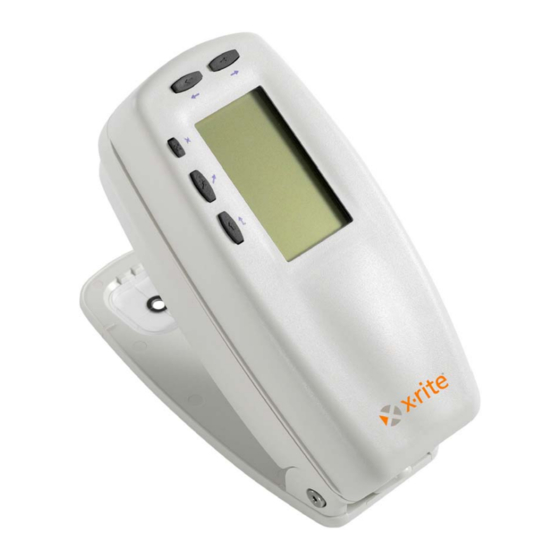
Charging Battery Pack Instrument I/O Serial Interface Attaching the Optional Security Cable Instrument Description The X-Rite 500 Series Spectrodensitometer is the most versatile and revolutionary hand-held color measurement instrument available today. The instrument relies on an integrated spectrophotometric engine, allowing accurate and precise measurements. -
Page 14: Features
C H A P T E R O N E Features Automatic Shut-Off To increase battery life, the instrument automatically turns itself off if it is not used within a user-defined time—between 10 and 120 seconds. See Setting Instrument Configuration, Section Four for more information. -
Page 15: Unpacking And Inspection
Your instrument was packaged in a specially designed carton to assure against damage. If shipment is necessary, the instrument should be packaged in the original carton. If the original carton is not available, contact X-Rite to have a replacement carton shipped to you. Shoe Lock Operation To take measurements with the instrument, you must unlock the shoe. -
Page 16: Applying Power
C H A P T E R O N E Applying Power The Battery switch—located on the bottom of the instrument—turns the instrument off and on during battery operation. When the AC adapter is attached, the instrument remains on and the battery switch has no affect. As an added feature to conserve battery life, the instrument automatically powers down when it is not in use. -
Page 17: Charging The Battery Pack
NOTE: Only use the AC Adapter supplied or the optional battery charger (X-Rite P/N 500CHG) to charge the battery pack. A "Low Battery" message appears on the display when the battery falls below approximately 25% of full charge. -
Page 18: Instrument I/O Serial Interface
C H A P T E R O N E Instrument I/O Serial Interface Your instrument can be connected to a computer or printer using an interface cable and adapter. X-Rite carries a variety of adapters to meet your requirements. To install the interface cabling: 1. -
Page 19: Attaching The Optional Security Cable
O V E R V I E W A N D S E T U P Attaching the Optional Security Cable An optional security cable is available from X-Rite for attaching the instrument to a fixed location. To install the security cable: 1. - Page 20 C H A P T E R O N E...
-
Page 21: Section 2 - User Interface
S P E C T R O D E N S I T O M E T E R User Interface What to Expect Navigation–Basic Key Operation Function Screen Using the Instrument What to Expect When the instrument is first powered-up, the main (top level) screen appears. -
Page 22: Tab Down Key
C H A P T E R T W O Tab Down key Advances the highlighted bar (reverse image) to the next available “tab stop.” A “tab stop” indicates an item that can be acted on further, such as a measurement or a setting option. -
Page 23: Function Screen
U S E R I N T E R F A C E Function Screen The instrument function screen consists of six main areas: Active Function, Options Menu, Measurement List, Measurement Data, User Dialog, and Current Status or Illum/Obs. Below is a brief description for each area of the function screen. -
Page 24: Measurement Data
C H A P T E R T W O Measurement Data The Measurement Data portion of the screen instantaneously displays measurement data for the active function. Measurement data that is out-of-range or unable to display in the space provided appears as " XXX ." User Dialog The User Dialog portion (bottom line, not including the status or illum/obs) indicates the current mode or... -
Page 25: Using The Instrument
U S E R I N T E R F A C E Using the Instrument There are four basic techniques used to navigate through the instrument screens, select functions and settings, and determine values. Opening a Menu or Function Opening a menu or a function gives you access to additional items related to the menu or specific information for a function. -
Page 26: Selecting From A List
C H A P T E R T W O Selecting from a List Many settings and functions allow you to select specific items from a list. Lists can be found in every type of screen: menus, editor, function screens, etc. To select an item from a list: 1. -
Page 27: Section 3 - Instrument Calibration
S P E C T R O D E N S I T O M E T E R Instrument Calibration General Information White Calibration Full Calibration General Information Under normal circumstances, the instrument should be calibrated at least once a day. Calibrating the instrument every day ensures the best measurement accuracy and stability. - Page 28 C H A P T E R T H R E E snugly with the target window opening centered over the white ceramic disk. White Patch Calibration Reference C A L I B R A T I O N W h i t e M e a s u r e w h i t e p a t c h o n c a l i b r a t i o n...
-
Page 29: Full Calibration
U S E R I N T E R F A C E Full Calibration The Full Calibration function is used to update the white and black calibration points in the instrument. To update calibration: 1. Repeatedly press the Tab Down key @ to highlight the Configuration option. - Page 30 C H A P T E R T H R E E 6. Press the Enter key # to open the Full Calibration screen. < Measure White > patch appears in the User dialog. 7. Position the instrument on the reference white patch (as explained earlier) and measure patch.
-
Page 31: General Information
S P E C T R O D E N S I T O M E T E R Setting Instrument Configuration General Information Language Active Functions Color Options (520, 528, 530 only) Density Options Calibration Options 4-10 Serial Port 4-12 Power Down 4-16... -
Page 32: Active Functions
C H A P T E R F O U R Language The Language configuration allows you to select the language you want to display on your instrument. To select a language: Language 1. Use the Tab keys $@ to highlight 2. -
Page 33: Color Options (520, 528, 530 Only)
S E T T I N G I N S T R U M E N T C O N F I G U R A T I O N 5. After edits are complete, press the Escape key ! to save and exit. -
Page 34: L*C*H° Method (528, 530 Only)
C H A P T E R F O U R 3. Use the Tab keys $@ to highlight the desired method, CIE or Hunter . 4. Press the Enter key # to save your settings and return to the Color Options menu. L*C*h°... -
Page 35: Cie94 Tolerancing (528, 530 Only)
S E T T I N G I N S T R U M E N T C O N F I G U R A T I O N 3. Use the Tab keys $@ to highlight the attribute you want to edit. -
Page 36: Precision
C H A P T E R F O U R 4. Press the Enter key # to access the Lightness or Chromaticity reference menu. 5. Use the Tab keys $@ to choose the desired digit (arrows above and below designated selection). Press the Enter key # to access the editor. -
Page 37: Density Options
North American graphic arts industry. This status is used to calibrate the instrument to the T-Ref™ color reference. • Status G⎯X-Rite Graphic Arts Response is a wideband response that is similar to Status T, except that it is more sensitive to denser yellow inks. -
Page 38: Precision
• Status A⎯ANSI Status A Response is used in the photofinishing applications. • Ax, Tx, and Ex responses closely match the X-Rite 400 series responses. • Status I ⎯Spectrodensitometric Response is computer corrected and designed for use with process inks on paper. -
Page 39: Gray Set
S E T T I N G I N S T R U M E N T C O N F I G U R A T I O N For example, Density data formatting for normal precision and high precision is shown below. Normal Precision High Precision Format... -
Page 40: Calibration Options
C H A P T E R F O U R • Standard - Normal measurement functionally occurs in auto color mode. This is the instrument’s factory setting. To select a gray set scale: 1. Use the Tab keys $@ to highlight Gray Set D e n s i t y O p t i o n s S t a t u s... -
Page 41: Enter Reflectances
S E T T I N G I N S T R U M E N T C O N F I G U R A T I O N 2. Press the Enter # key open the Calibration Options menu. Enter Reflectances The Enter Reflectances function is used to manually edit the white calibration reflectance values. -
Page 42: Cal Alert
C H A P T E R F O U R Cal Alert To set the calibration alert settings: 1. Use the Tab keys $@ to highlight Cal Alert C a l i b r a t i o n O p t i o n s F u l l C a l i b r a t i o n E n t e r R e f l e c t a n c e s C a l A l e r t : 2 4 h r s... -
Page 43: Baud Rate
Protocol – Select the desired protocol. • Emulation – Determines the output characteristics of the instrument. Selecting 400 Series emulates the density output format of the X-Rite 400 series instruments. Selecting Normal outputs the normal format of the instrument. To open the Serial Port menu: 1. -
Page 44: Auto Xmit
C H A P T E R F O U R • CTS – CTS/RTS hardware hand shaking used. This method ensures the instrument is working before sending a hand shake. • BUSY – BUSY hand shaking used. To set the hand shake method: Hand Shake 1. -
Page 45: Separator
S E T T I N G I N S T R U M E N T C O N F I G U R A T I O N Separator To determine the separator character: 1. Use the Tab keys $@ to highlight Separator S e r i a l P o r t B a u d R a t e... -
Page 46: Emulation
C H A P T E R F O U R 2. Press the Enter key # to access the editor. 3. Use the Tab keys $@ to highlight the desired protocol, RCI or ICP . 4. Press Enter key # to save the setting and return to the Serial Port menu. -
Page 47: Speed Read
S E T T I N G I N S T R U M E N T C O N F I G U R A T I O N 3. To set the power down time (in seconds), use the Tab keys $@ to choose the desired digit (arrows above and below designated selection). -
Page 48: Contrast
X-Rite’s Technical Support staff for diagnostic purposes. • Error Log – Used by X-Rite's Technical Support to identify where an error condition occurred in the instrument. To open the Display options menu: 1. Use the Tab keys $@ to highlight... -
Page 49: Orientation
S E T T I N G I N S T R U M E N T C O N F I G U R A T I O N 2. Press the Enter key # to access the Set Display Contrast menu. -
Page 50: Patch Smarts
C H A P T E R F O U R 2. Press the Enter key # to access the editor. 3. Use the Tab keys $@ to highlight the desired setting, On or Off . 4. Press Enter key # to save the setting and return to the Display menu. -
Page 51: User Configuration
S E T T I N G I N S T R U M E N T C O N F I G U R A T I O N appropriate type (paper, solid, etc). When set to Off, the instrument simply sequences through the measurement steps with no attempt at identifying the measurement type. -
Page 52: Load Factory Defaults
4. Press Enter key # to save the setting and return to the Configuration menu. Load Factory Defaults The 500 series instrument can have its factory defaults reloaded whenever required. All configuration settings and function options are reset to their original state. Restoring the defaults also clears any reference data stored in the instrument. - Page 53 S E T T I N G I N S T R U M E N T C O N F I G U R A T I O N – M A I N M E N U – L o a d D e f a u l t s X - R i t e D e n s i t y...
- Page 54 C H A P T E R F O U R 4-24...
-
Page 55: General Information
S P E C T R O D E N S I T O M E T E R Instrument Functions General Information Density Color Match 5-17 5-23 Trap 5-31 Print Contrast 5-37 Hue/Grayness 5-42 Paper Indices 5-46 Compare 5-51 Electronic Function Selection 5-56 General Information... -
Page 56: Density Function
C H A P T E R F I V E Density Function The instrument can report density and density difference with or without paper subtracted. You should select the Density Display Mode and set the Options before measuring. Density Measurement Mode Your instrument can evaluate density data two different ways: as straight density (absolute) measurement data, or as density difference (minus reference) measurement data. -
Page 57: Measuring Paper
I N S T R U M E N T F U N C T I O N S measurement is displayed. The Red, Green, Blue, and Orange components only appear when HiFi status is selected. Mode The Mode allows you to select between Absolute and –Paper. When you select density minus paper as the mode, you must provide paper data before taking a sample measurement. -
Page 58: Measuring/Editing A Density Reference
C H A P T E R F I V E O p t i o n s D E N - R E F 0 1 V 0.06 P a p e r C 0.06 S a m p l e M 0.06 R e f e r e n c e <... - Page 59 I N S T R U M E N T F U N C T I O N S Reference NOTE: will not appear in the measurement list unless DEN–REF01 is selected as the active density mode. Refer to Density Measurement Mode earlier in this section.
-
Page 60: Measuring A Density Sample
C H A P T E R F I V E 3. Press the Enter key # to move the highlight to the data side of the screen. < Enter Ref > appears in the user dialog. Clear Ref and pressing Enter key # can NOTE: Highlighting quickly clear current reference data. - Page 61 I N S T R U M E N T F U N C T I O N S Density -Paper and Actual Measurements If you set the density options to Auto (or a single color) and - Paper , your measurement data appears like this: D E N S I T Y O p t i o n s Single absolute -paper...
- Page 62 C H A P T E R F I V E News 3-Color Measurements If you set the User Configuration option to News 3-Color and measure a three color overprint patch, your measurement data appears like this: D E N S I T Y O p t i o n s Y 0.55 M 0.52...
-
Page 63: Color Function (520, 528, 530 Only)
I N S T R U M E N T F U N C T I O N S Color Function (520, 528, 530 only) The 520, 528, and 530 instruments report colorimetric data absolute or colorimetric data difference. The 530 instrument also has the added capability of reporting reflectance data. - Page 64 C H A P T E R F I V E 10nm increments from 400nm to 700nm. The 520 instrument limits selection to XYZ and L*a*b*. ΔE Method The instrument supports three tolerancing methods: CMC, Lab, and CIE94. Displayed data automatically updates to the selected method after you exit.
-
Page 65: Selecting Illuminant (528, 530 Only)
I N S T R U M E N T F U N C T I O N S 3. Use the Tab keys $@ to move the highlight to desired setting. 4. Press the Enter key # to save highlighted setting. 5. -
Page 66: Measuring/Editing A Color Reference
C H A P T E R F I V E Measuring/Editing a Color Reference The reference function is used to enter color reference data into the instrument using a sequence or match method. Up to 16 references can be stored and accessed in the instrument. -
Page 67: Measuring A Color Sample
I N S T R U M E N T F U N C T I O N S 3. Press the Enter key # to alternate between Match 4. Center the target window over the first reference (or replacement reference if a match), and lower the instrument to take a reading. - Page 68 C H A P T E R F I V E You are now ready to begin taking measurements to check color values. The type of measurement data that displays depends on the way you set up your instrument earlier in this section. To measure a sample: Sample 1.
-
Page 69: Viewing L*A*B* Data In The Graph Mode
I N S T R U M E N T F U N C T I O N S Viewing L*a*b* Data in the Graph Mode The 528 and 530 instruments can display a graph when L*a*b* is selected as the Color Space option. Graphical data is viewable as actual or difference. -
Page 70: Viewing Reflectance Data And Reflectance Graph (530 Only)
C H A P T E R F I V E Viewing Reflectance Data and Reflectance Graph (530 only) The 530 instrument has the added capability of displaying a reflectance graph and data when Reflectance is selected as the Color Space option. Data is displayed in 10nm increments, from 400 to 700 nanometers. -
Page 71: Match Function (528, 530 Only)
16 matches are displays based on Delta-E difference. The instrument can store over 1,400 references across a total of 10 groups. When used in conjunction with X-Rite’s ColorMail Express (CMX), color libraries, such as a PANTONE® database can easily be downloaded to the instrument and used for reference matches. - Page 72 C H A P T E R F I V E ΔE Method The instrument supports three tolerancing methods: CMC, Lab, and CIE94. Displayed data automatically updates to the selected method after you exit. CMC- is an ellipsoidal tolerance method that attempts to correlate small measured color differences with visual assessment.
- Page 73 I N S T R U M E N T F U N C T I O N S To create a group: 1. With the Match Options menu displayed, press the Tab Up key $ or Tab Down key @ to highlight Active Group option.
-
Page 74: Measuring References
C H A P T E R F I V E Measuring References The reference function is used to measure reference data into a selected group. A total of 1,424 references can be stored in the instrument. The default reference name that is generated after a measurement (i.e., Ref0001) can be change to a specific color name or code. -
Page 75: Matching Samples
I N S T R U M E N T F U N C T I O N S 4. To enter a custom name for the reference, press the Enter key # with the reference number highlighted. The highlight moves to the reference name on the right side of the screen. - Page 76 C H A P T E R F I V E 3. The actual sample data is displayed while the instrument is held down. After the instrument is released, the reference match list appears (maximum of 16). M A T C H : G r o u p 1 O p t i o n s R e f 0 0 1 0 Δ...
-
Page 77: Dot Function (508, 518, 520, 528, 530 Only)
I N S T R U M E N T F U N C T I O N S Dot Function (508, 518, 520, 528, 530 only) Dot is calculated using either the Murray-Davies formula or the Yule-Nielson formula. Murray-Davies simply calculates dot by comparing the density of the tint minus paper with the density of the solid minus paper. -
Page 78: Dot Measurement Mode
C H A P T E R F I V E Dot Measurement Mode Your instrument can evaluate dot data two different ways: as Dot Area or Dot Gain. Pressing the Enter key # with the Dot mode highlighted alternates between Dot Area and Dot Gain. - Page 79 I N S T R U M E N T F U N C T I O N S NOTE: As halftones become lighter and lighter (< 25%), the resulting "color" tends towards the shade of the substrate itself. This may be different from the shade of the ink or plate emulsion.
- Page 80 C H A P T E R F I V E 3. Use the Tab keys $@ to highlight the desired number and press the Enter key # to exit the editor. 4. To select On/Off status, press the Enter key # with (Murray-Davies) or (Yule-Nielson) highlighted.
- Page 81 I N S T R U M E N T F U N C T I O N S 9. Move highlight to re-measure any component, or Save n highlight . The calculated value is displayed. Press Enter key # to save. Save n NOTE: If an error message appears when is highlighted, the...
-
Page 82: Measuring Paper
C H A P T E R F I V E Measuring Paper The instrument takes the density value of the paper and automatically subtracts it from subsequent solid and dot measurements. The paper measurement values are applied to all functions that support minus paper. D O T A R E A O p t i o n s V 0.09... - Page 83 I N S T R U M E N T F U N C T I O N S To perform a dot measure: 1. If not selected, press the Tab Up key $ or Tab Down key @ to highlight Solid .
- Page 84 C H A P T E R F I V E Dot Gain Measurements If you set your color option to Auto (or a single color), your measurement data appears like this: D O T G A I N — 7 5 % O p t i o n s P a p e r Corresponding Reference...
-
Page 85: Trap Function (518, 528, 530 Only)
I N S T R U M E N T F U N C T I O N S Trap Function (518, 528, 530 only) The Trap function determines how well one ink prints over another ink (overprinting). You should select the Trap Display Mode and set the Options before measuring. -
Page 86: Measuring/Editing Dmax Procedure
C H A P T E R F I V E Brunner Trap formula − − 1 10 × − − 1 10 Where: • = Density of overprint - paper • = Density of 2 ink - paper • = Density of 1 ink - paper •... - Page 87 I N S T R U M E N T F U N C T I O N S T R A P D M A X O p t i o n s V 1.58 B l a c k C y a n C 1.59 M a g e n t a...
-
Page 88: Measuring Paper
C H A P T E R F I V E Measuring Paper The instrument takes the density value of the paper and automatically subtracts it from subsequent trap measurements. Paper is always subtracted from the trap function. T R A P - R E F O p t i o n s V 0.13 P a p e r... -
Page 89: Saving Trap Data As A Reference
I N S T R U M E N T F U N C T I O N S 4. Lower unit to target window and hold closed. Once measurement data is displayed, release the unit. Ink1 5. Make sure is highlighted on the screen and center the target window on first ink down patch. - Page 90 C H A P T E R F I V E 2. Press the Enter key # to access the References Option screen. Clear Ref and pressing the Enter key # can NOTE: Highlighting quickly clear the current reference data. Edit Ref 3.
-
Page 91: Print Contrast Function (518, 528, 530 Only)
I N S T R U M E N T F U N C T I O N S Print Contrast Function (518, 528, 530 only) Print Contrast provides you with the ability to monitor the ¾ tone area and is useful when determining the optimum printing density. -
Page 92: Measuring Paper
C H A P T E R F I V E Single color measurement method measures and updates the specific color you selected. Red, Green, Blue, and Orange only appear when HiFi status is selected. Mode The Mode allows you to select between Absolute and – Paper. -
Page 93: Measuring Print Contrast Procedure
I N S T R U M E N T F U N C T I O N S To measure paper: 1. If not selected, press the Tab Up key $ or Tab Down key @ to highlight Paper . -
Page 94: Saving Print Contrast Data As A Reference
C H A P T E R F I V E 3. Continue with remaining solid patch measurements or center the target window over the 75% tint patch that corresponds to the measured solid. 4. Lower unit to target window and hold closed. Once measurement data is displayed, release the unit. - Page 95 I N S T R U M E N T F U N C T I O N S 2. Press the Enter key # to access the References Option screen. Clear Ref and pressing the Enter key # can NOTE: Highlighting quickly clear the current reference data.
-
Page 96: Hue/Grayness Function (518, 528, 530 Only)
C H A P T E R F I V E Hue/Grayness Function (518, 528, 530 only) The instrument can report hue error/grayness and hue error/grayness difference with or without paper subtracted. Hue/Gray measures the selected ink through all three filters (cyan, magenta, and yellow). Hue Error and Grayness are calculated using the following formulas. - Page 97 I N S T R U M E N T F U N C T I O N S To set option: 1. With the Mode editor displayed, press the Tab keys $@ to move the highlight to desired setting. 2.
-
Page 98: Measuring/Editing A Hue/Gray Reference
C H A P T E R F I V E Measuring/Editing a Hue/Gray Reference The reference function is used to enter hue error and grayness reference data into the instrument. The reference data is stored in the instrument until changed. Hue/Gray reference values are then compared to Hue/Gray measurements and the difference displayed. - Page 99 I N S T R U M E N T F U N C T I O N S 6. Use the Tab keys $@ to highlight desired number and press Enter key # to exit editor. Save & Exit 7.
-
Page 100: Paper Indices Function (528, 530 Only)
C H A P T E R F I V E Paper Indices Function (528, 530 only) The instrument can report cast, brightness, and reflectance paper indices as absolute or difference data. The Cast value represents the difference between the highest and lowest reflectance values. - Page 101 I N S T R U M E N T F U N C T I O N S P A P E R I N D I C E S — R E F S a m p l e M e a n C l e a r R e f R e f e r e n c e...
-
Page 102: Measuring Paper Indices Samples
C H A P T E R F I V E 7. Use the Tab keys $@ to highlight desired number and press Enter key # to exit editor. Save & Exit 8. After edits are complete, highlight and press Enter key #. NOTE: The instrument automatically rounds the entered value to the nearest whole percentage. -
Page 103: Statistical Data
I N S T R U M E N T F U N C T I O N S Paper Indices Difference Measurements A “negative” value indicates that the obtained paper index of the sample was smaller than that of the reference. The opposite is true for a positive value. - Page 104 C H A P T E R F I V E Measuring Samples in Statistics Mode 1. Center target window on sample and lower instrument to take a measurement. Calculation data appears and the measurement counter increments. P A P E R I N D I C E S S a m p l e M e a n Measurement Counter...
-
Page 105: Compare Function (520, 528, 530 Only)
I N S T R U M E N T F U N C T I O N S Compare Function (520, 528, 530 only) The Compare function is used to compare sample measurements to previously stored references. A total of 24 references can be stored in the instrument's Compare function. -
Page 106: Setting Up Compare References
C H A P T E R F I V E Observer Angle The instrument supports both 2° and 10° observer angles. The 520 only has the 2° angle available. Refer to Color Function earlier in this section for additional information on observer angles. To set ΔE or Observer Angle option: 1. - Page 107 I N S T R U M E N T F U N C T I O N S To set up a reference: 1. If not selected, press the Tab Up key $ or Tab Down key @ to highlight Reference 2.
-
Page 108: Comparing Samples
C H A P T E R F I V E or Tab Down key @ to highlight illuminant/observer menu, and press Enter key # to select combination. NOTE: The Match function database can be accessed at anytime by and pressing the Enter key #. highlighting Match 9. - Page 109 I N S T R U M E N T F U N C T I O N S Color Compare Measurements If the matched reference option compares color, your measurement data appears like this: Reference used for comparison C O M P — R E F 0 1 O p t i o n s C o l o r ΔE 0.12...
-
Page 110: Setting Options
C H A P T E R F I V E Electronic Function Selection (518, 528, 530 only) EFS automatically recognizes the patch type measured without manually selecting the function. The "smart" recognition of Paper, Dot, Solid, PC, Density, Trap, H/G, and Color is contained in this function. -
Page 111: Measuring Samples
I N S T R U M E N T F U N C T I O N S To set options: 1. With the EFS Options menu displayed, press the Tab Up key $ or Tab Down key @ to highlight OP Setting , Ref 3 Setting , or Mode option. - Page 112 C H A P T E R F I V E 5-58...
-
Page 113: Repair Information
UV Filter Cap Kit Installation Repair Information ® The X-Rite 500 series instrument is covered by a three- year limited warranty—excluding battery pack—and should be referred to factory or authorized service center for repairs within the warranty period. Attempts to make repairs within this time frame may void the warranty. -
Page 114: Cleaning The Instrument
C H A P T E R S I X Cleaning the Instrument Your instrument requires very little maintenance to achieve years of reliable operation. However, to protect your investment and maintain reading accuracy, a few simple-cleaning procedures should be performed from time to time. - Page 115 S E R V I C E A N D G E N E R A L M A I N T E N A N C E Battery Pack Replacement To replace the battery pack: 1. Rotate the shoe stop 90° and carefully turn the instrument over.
-
Page 116: Aperture And Polarization Kit Installation
C H A P T E R S I X Aperture and Polarization Kit Installation (Excludes Micro-Spot instrument) The 500 series instrument was designed to allow you to quickly change the aperture and target window. X-Rite provides three aperture kits especially designed for the 500 series instrument. - Page 117 S E R V I C E A N D G E N E R A L M A I N T E N A N C E 5. Press the tool down (approx. 12mm) on the aperture with slight pressure. A low, click is heard when properly seated.
- Page 118 C H A P T E R S I X 9. Locate old optics cap for non-polarized installation or new optics cap for polarized installation. Align triangle in cap with the diamond in the bottom housing. Rotate optics cap clockwise until the triangle on the cap meets the triangle/circle on the bottom housing.
-
Page 119: Uv Filter Cap Kit Installation
S E R V I C E A N D G E N E R A L M A I N T E N A N C E UV Filter Cap Kit Installation (Excludes Micro-Spot instrument) To install UV filter optics cap: 1. - Page 120 C H A P T E R S I X...
-
Page 121: Instrument Specifications
1050 grams (2.3 lbs.) Accessories Provided Calibration Reference, Manual, AC Adapter, Carrying Case Usage Indoor only Altitude 2000m Pollution Degree Overvoltage Category II NOTE: X-Rite reference standards are traceable to the National Institute of Standards and Technology through Munsell Color Science Laboratory RIT. -
Page 122: Error Messages
C H A P T E R S E V E N Error Messages Errors encountered during a measurement are displayed in the User Dialog. All errors are accompanied by a long beep. Any errors (except < Low Battery >) encountered during a measurement cancel that measurement;... - Page 124 Corporate Headquarters - USA 4300 44th St. SE Grand Rapids, MI 49512 Phone 1 800 248 9748 or 1 616 803 2100 Fax 1 800 292 4437 or 1 616 803 2705 Corporate Headquarters - Europe Althardstrasse 70 8105 Regensdorf Switzerland Phone (+41) 44 842 24 00 Fax (+41) 44 842 22 22...
Need help?
Do you have a question about the 500 Series and is the answer not in the manual?
Questions and answers