ABB REF542plus Operator's Manual
Multifunction protection and switchgear control unit
Hide thumbs
Also See for REF542plus:
- Installation and commissioning manual (80 pages) ,
- Manual (66 pages)
Table of Contents
Advertisement
Quick Links
Advertisement
Table of Contents

Related Manuals for ABB REF542plus


Summary of Contents for ABB REF542plus
- Page 1 REF542plus Multifunction Protection and Switchgear Control Unit Operator's manual...
-
Page 3: Table Of Contents
3. HMI features..............11 3.1. Control area................ 11 3.2. Info and Menu area............13 3.3. REF542plus status information area......... 15 4. Behavior at power up............17 5. Control modes..............19 5.1. Available control modes............. 19 5.2. - Page 4 REF542plus 1MRS755869 Multifunction Protection and Switchgear Control Unit Operator's manual 13.7. Optical output commissioning page........47 14. Connection to PC............. 49 14.1. Optical to RS232 converter cable........49 14.2. Downloading a configuration..........49 14.2.1.
- Page 5 Copyrights The information in this document is subject to change without notice and should not be construed as a commitment by ABB Oy. ABB Oy assumes no responsibility for any errors that may appear in this document. In no event shall ABB Oy be liable for direct, indirect, special, incidental or...
-
Page 7: Introduction
This manual Before attempting any operation with REF542plus, read this manual carefully first. This manual describes how to use the interface of REF542plus (LD HMI, Local Detached Human Machine Interface). Note that HMI views and pictures are to be considered exemplary. -
Page 8: Intended Audience
1VTA100172-Rev 1, en 01.11.2002 First release 1VTA100172-Rev 2, en 22.10.2003 Updated to version 4D02 1VTA100172-Rev 3, en 03.05.2004 Updated 1VTA100172-Rev 4, en 04.04.2005 Updated 28.02..2006 Document updated language layout Applicability This manual is applicable to REF542plus Release 2.0, software version V4D02. -
Page 9: Safety Information
1MRS755869 REF542plus Multifunction Protection and Switchgear Control Unit Operator's manual Safety information Dangerous voltages can occur on the connectors, even though the auxiliary voltage has been disconnected. Non-observance can result in death, personal injury or substantial property damage. Only a competent electrician is allowed to carry out the electrical installation. -
Page 11: Hmi Features
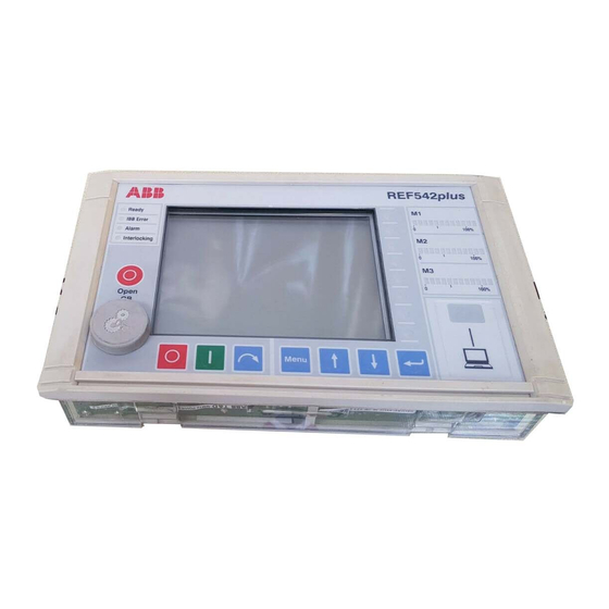
Operator's manual HMI features The REF542plus HMI is shown in Fig. 3.-1. The HMI features a back illuminated LCD, 8 push buttons, several LEDs and an electronic key sensor. The language of the display, when available, can be selected via the Operating Tool. - Page 12 Control Key: this is dedicated to the control modes. It allows changing the operating mode of REF542plus. The different operating modes discipline the access to the primary objects by the different REF542plus interfaces (HMI and SCADA). When required, a Super User key to access both...
-
Page 13: Info And Menu Area
The Super User key is also needed to access the commissioning test mode. The password codes stored in the key can be customized in each REF542plus for access restriction purposes. SLD view: this is the graphical part of the LCD. This part shows the single line diagram of the switchgear. - Page 14 LED to a specific condition is done with the Operating Tool. Optical interface: This is the optical serial interface port to connect REF542plus to a personal computer. By using the appropriate cable and the Operating Tool, the following actions are possible: Download a configuration into the unit.
-
Page 15: Ref542Plus Status Information Area
(FUPLA is not running). Network Communication. This LED is meaningful only when the REF542plus is equipped with a communication module. When a communication module is detected the LED turns on to green. If the module is not detected or fails, the LED turns red. -
Page 17: Behavior At Power Up
Unit Operator's manual Behavior at power up Before energizing the switchgear, verify that the REF542plus protection functions are properly set and that the unit is properly working (READY LED green). At power up, the HMI unit shows on the LCD for a few seconds the... -
Page 19: Control Modes
1MRS755869 REF542plus Multifunction Protection and Switchgear Control Unit Operator's manual Control modes 5.1. Available control modes Local Control It is possible to control the circuit breaker and other primary objects from the HMI using the object control buttons. Open and close operations are possible only if the interlocking logic programmed into the unit allow them. - Page 20 REF542plus 1MRS755869 Multifunction Protection and Switchgear Control Unit Operator's manual A051340 Fig. 5.2.-1 Changing the control mode by using the control key...
-
Page 21: Operating The Primary Objects
Press to close the selected object. Only primary objects controlled directly by REF542plus can be selected. For example, REF542plus will show the correct position of a manual disconnect switch after an operation, but it will not be possible to select it. -
Page 23: Viewing And Resetting Alarms
1MRS755869 REF542plus Multifunction Protection and Switchgear Control Unit Operator's manual Viewing and resetting alarms 7.1. Viewing alarms The presence of an alarm, when latched, is indicated by the alarm LED turned on or by one of the 8 x 4 pages user programmable LED’s turned on to red. - Page 24 REF542plus 1MRS755869 Multifunction Protection and Switchgear Control Unit Operator's manual Some alarms might not be reset before the cause that generated it has been removed. For example, an alarm due to an error in the tripping circuit (coil supervision) cannot be reset before the tripping coil is replaced. Whereas an alarm generated by a trip of a protection function is normally reset with this procedure.
-
Page 25: Viewing Measurements
Multifunction Protection and Switchgear Control Unit Operator's manual Viewing measurements REF542plus offers complete measurements set to the user. To view the measurements, select the measurement menu with the navigation button. Use the UP and DOWN buttons to browse the measurement pages. - Page 26 REF542plus 1MRS755869 Multifunction Protection and Switchgear Control Unit Operator's manual A051343 Fig. 8.-1 Measurements visualization The available measurements depend upon the analogue input module type and the unit configuration.
-
Page 27: Viewing Events
Operator's manual Viewing events REF542plus records the last 30 protection events (start, trips, block and other). This internal memory is managed as a circular buffer, for example the 31st event overwrites the 1st oldest one. In case of a power loss, events are kept because they are stored in the non-volatile memory. -
Page 29: Viewing And Changing The Protection Settings
1MRS755869 REF542plus Multifunction Protection and Switchgear Control Unit Operator's manual Viewing and changing the protection settings 10.1. Viewing the protection settings The protection functions currently installed in the unit can be seen in the menu protection functions. Select the menu protection functions with the navigation push buttons. -
Page 30: Changing The Protection Parameters
REF542plus 1MRS755869 Multifunction Protection and Switchgear Control Unit Operator's manual The procedure to change the protection mode is identical to changing the control mode. At first, the menu E-Key must be selected. Then the protection key must be placed in the electronic key sensor. Select then the required... - Page 31 1MRS755869 REF542plus Multifunction Protection and Switchgear Control Unit Operator's manual A051347 Fig. 10.2.2.-1 Changing protection parameters Press again to leave the protection functions menu. The unit will then ask what to do with the changes: The following screen will appear: A051348 Fig.
-
Page 32: Changing The Active Parameter Set
REF542plus 1MRS755869 Multifunction Protection and Switchgear Control Unit Operator's manual Select the desired choice with Up or Down and then press ENTER to confirm it. The meaning of the choices is as follows: Store permanently: The new parameters are stored in the unit internal memory. -
Page 33: Viewing And Changing Control Parameters
1MRS755869 REF542plus Multifunction Protection and Switchgear Control Unit Operator's manual 10.2.4. Viewing and changing control parameters Select the Control menu with the navigation push buttons and highlight the desired control function. Press ENTER to select it. Press again the cursor will automatically go to the first control parameter. Use the Up or Down button to modify the parameter as wished. -
Page 35: Setting The Time And Date
1MRS755869 REF542plus Multifunction Protection and Switchgear Control Unit Operator's manual Setting the time and date During commissioning, the internal time and date of the unit should be set to the current values. There are a few differences according to the unit configuration. -
Page 37: Command Page
Operator's manual Command page From this page, it is possible to access the HMI command objects configured in the application software of REF542plus. For more information on these objects, refer to Operating Tool user manual. A051352 Fig. 12.-1 Command page... -
Page 39: Ref542Plus Commissioning Mode
Operator's manual REF542plus commissioning mode The commissioning test mode allows accessing all the digital and analogue inputs and outputs of REF542plus. This mode is independent of the REF542plus application. This working mode has been designed to make easier the wiring verification. -
Page 40: Binary Input Commissioning Page
REF542plus 1MRS755869 Multifunction Protection and Switchgear Control Unit Operator's manual A051353 Fig. 13.-1 Commissioning mode display 13.1. Binary input commissioning page This page displays the current status of the binary input channels on the binary IO modules. There are 14 binary inputs per module available. For the binary inputs numbering see Section 18.2. -
Page 41: Binary Output Commissioning Page
1MRS755869 REF542plus Multifunction Protection and Switchgear Control Unit Operator's manual A051354 Fig. 13.1.-1 Binary inputs commissioning page 13.2. Binary output commissioning page On this page, it is possible to force the status of the binary outputs. All the outputs can be driven with the exception of the watchdog. -
Page 42: Analog Input Commissioning Page
REF542plus 1MRS755869 Multifunction Protection and Switchgear Control Unit Operator's manual A051355 Fig. 13.2.-1 Binary outputs commissioning page 13.3. Analog input commissioning page This page shows the analog measurements acquired by the analog input module. The shown values are independent on the rated primary current or... - Page 43 1MRS755869 REF542plus Multifunction Protection and Switchgear Control Unit Operator's manual values taking into consideration as nominal values of the secondary windings 1 Amp and 100 V. If the 5 Amp current inputs are connected applying the nominal rated current, it will be shown 1 A.
-
Page 44: Analog Output 4- 20 Ma Commissioning Page
REF542plus 1MRS755869 Multifunction Protection and Switchgear Control Unit Operator's manual A051357 Fig. 13.3.-2 Analog inputs commissioning page for the 6 sensor module connected to 3 voltage divider and 3 Rogowski coils 13.4. Analog output 4- 20 mA commissioning page This page allows setting the value of the analog channels in the 4-20 mA module. - Page 45 1MRS755869 REF542plus Multifunction Protection and Switchgear Control Unit Operator's manual A051358 Fig. 13.4.-1 A 4-20 mA analog outputs commissioning page...
-
Page 46: Analog Input 4-20 Ma Commissioning Page
REF542plus 1MRS755869 Multifunction Protection and Switchgear Control Unit Operator's manual 13.5. Analog input 4-20 mA commissioning page From this page, it is possible to read the analog measurements of the Analog Input 4-20 mA module. The shown measurements will be depending on the connected sensor type. -
Page 47: Optical Inputs Commissioning Page
1MRS755869 REF542plus Multifunction Protection and Switchgear Control Unit Operator's manual 13.6. Optical inputs commissioning page This page displays the status of the optical inputs on the main module. This mode is available only with main modules equipped with the optical inputs (1VCF751021R0803, X74 only and 1VCF751021R0801 for all). - Page 48 REF542plus 1MRS755869 Multifunction Protection and Switchgear Control Unit Operator's manual The value can be selected with UP , DOWN A051361 Fig. 13.7.-1 Optical output commissioning page...
-
Page 49: Connection To Pc
Operator's manual Connection to PC 14.1. Optical to RS232 converter cable A special cable with an optical interface is needed to connect REF542plus to a serial port of a PC. This cable is available from ABB. Fig. 14.1.-1 REF542plus serial cable 14.2. -
Page 50: Serial Port Settings
REF542plus 1MRS755869 Multifunction Protection and Switchgear Control Unit Operator's manual 14.2.1. Serial port settings A051364 Fig. 14.2.1.-1 Setting the communication parameter of the serial port Select the COM port where the RS232/optical cable is plugged in. Apply the following settings:... - Page 51 1MRS755869 REF542plus Multifunction Protection and Switchgear Control Unit Operator's manual Open the application file with the Operating Tool and change it in the hardware settings. A051365 Fig. 14.2.1.-2 Changing the Base Unit address Via the HMI menu > Service page > Communication > HMI PORT A051366 Fig.
-
Page 52: Uploading The Configuration
14.3. Uploading the configuration With the Operating Tool, it is possible to upload the current configuration inside REF542plus. Set the Operating Tool and the PC as for the download and click the menu Transfer/load from REF542plus. Please note: The uploaded configuration overwrites the current one inside the Operating Tool. -
Page 53: Uploading Other Information
Unit Operator's manual 14.4. Uploading other information With the Operating Tool, other information can be uploaded from REF542plus. Different data can be uploaded: The fault recorder file The binary input status The binary output status The measurements The software version All this data is accessible with the Operating Tool from the transfer menu. -
Page 55: Troubleshooting
1MRS755869 REF542plus Multifunction Protection and Switchgear Control Unit Operator's manual Troubleshooting 15.1. Error messages Base Unit not responding, communication corrupted or wrong slave address When the HMI is not able to communicate with the Base Unit, the following information appears on the LCD: A051367 Fig. - Page 56 REF542plus 1MRS755869 Multifunction Protection and Switchgear Control Unit Operator's manual A051437 Fig. 15.1.-2 HMI test page Select HMI <-> Base Unit address scanning menu item and press ENTER. The HMI will start polling all the addresses to find the connected Base Units.
- Page 57 1MRS755869 REF542plus Multifunction Protection and Switchgear Control Unit Operator's manual A051438 Fig. 15.1.-3 HMI is polling the Base unit addresses Select the HMI <-> Base Unit address to change the address to be polled. A051439 Fig. 15.1.-4 Changing the Base Unit address to be polled.
- Page 58 Multifunction Protection and Switchgear Control Unit Operator's manual Fig. 15.1.-5 HMI test page REF542plus is without configuration when the following message appears: A051441 Fig. 15.1.-6 REF542plus without configuration Solution: Download the configuration into the unit by using the serial cable and the Operating Tool.
- Page 59 Multifunction Protection and Switchgear Control Unit Operator's manual A051442 Fig. 15.1.-7 REF542plus configuration is not stored in the unit internal memory Solution: Try to download the configuration again. If after two or three attempts the error remains, contact ABB. Wrong configuration The following message appears when a not correct configuration has been downloaded in the Base Unit.
-
Page 60: Clearing The Configuration Inside The Unit
Clearing the configuration inside the unit In some cases, there might be the need to delete the configuration stored inside the REF542plus. For example, when the RED alarm is on, it is not possible to download a new configuration inside REF542plus. The following... - Page 61 REF542plus has voltage at both inputs indicating the primary object position Solution: Check the wiring of the primary object. Verify that REF542plus connectors are properly inserted and tightened. Note: When the primary object in such an undefined positions, issuing an open command will activate the open coil on the circuit breaker.
-
Page 63: Terminology
1MRS755869 REF542plus Multifunction Protection and Switchgear Control Unit Operator's manual Terminology Term Description Ethernet Physical communication network to transfer Internet data of the REF542plus to the PC and back. Modbus By extension, communication board implementing the Modbus protocol for REF542plus. -
Page 65: Abbreviations
Global Positioning System Human-Machine Interface Identification International Electrotechnical Commission Internet Protocol Lon Application Guide Liquid crystal display Logical Device Light-Emitting Diode Local operating network Micro controller SCADA Supervision, Control and Data Acquisition Single-line diagram Data communication protocol developed by ABB Voltage transformer... -
Page 67: Appendix A: Connection Diagrams
Unit Operator's manual Appendix A: Connection diagrams The pictures below show the connections plate for REF542plus both in the wide and standard housing versions. The wide housing version can house three binary input and output modules; the communication module, the analog output module or alternatively the analog 4-20 mA input module. - Page 68 REF542plus 1MRS755869 Multifunction Protection and Switchgear Control Unit Operator's manual A051447 Fig. 18.-2 REF542plus standard housing connections plate with mixed analog input connector Table 18.-1 summarizes the connectors. Table 18.-1 Connectors Connector Meaning Base Unit power supply First BIO, input...
-
Page 69: Analog Inputs
Sensor 8 18.1. Analog Inputs REF542plus can have a maximum of 8 analog input channels. These inputs are divided into three measurement groups: Measurement Group 1: channel 1, channel 2, channel 3 Measurement Group 2: channel 4, channel 5, channel 6... - Page 70 REF542plus 1MRS755869 Multifunction Protection and Switchgear Control Unit Operator's manual The Rogowsky coil can be used for current sensing. The correct ratio of the Rogowsky coil is selected with the Operating Tool. The resistive divider can be used for voltage sensing. The ratio is selected with the Operating Tool. The physical input on the unit is the same both for voltage and current sensing, the selection is done via the Operating Tool.
- Page 71 1MRS755869 REF542plus Multifunction Protection and Switchgear Control Unit Operator's manual Table 18.1.-1 Connection table for conven tional instrument transformers (Continued) T5/3 T3/1 T1/R T1/1 T8/1 T4/3 T2/B T2/2 T6/3 T7/B T7/2 T7/A T4/B T4/2 T2/3 T6/B T6/2 T7/R T7/3 T7/B...
-
Page 72: Binary Inputs And Outputs
X30 (inputs), X31 (outputs) for the second module. X40 (inputs), X41 (outputs) for the third module, available with the wide housing only. REF542plus can be equipped with two different types of binary inputs and outputs modules: static or with electromechanical relays. 18.2.1. -
Page 73: Electromechanical
In the electromechanical module, digital inputs are implemented with optocouplers and digital outputs are implemented with electromechanical relays. REF542plus can be equipped with 2 different electromechanical module types, BIO2 and BIO3. The modules are functionally equivalent, with slight variations. These modules are available in different versions. For more information, refer to the REF542plus Technical Catalogue. - Page 74 REF542plus 1MRS755869 Multifunction Protection and Switchgear Control Unit Operator's manual Table 18.2.2.1.-1 BIO3 types and codes (Continued) BIO3 Code Description 1VCF750132R0801 Binary I/O3 - 20..90 VDC/14 VDC Standard with interconnected '-' on inputs 1VCF750132R0803 Binary I/O3 - 20..90 VDC/14 VDC with Static...
-
Page 75: Other Connections
1MRS755869 REF542plus Multifunction Protection and Switchgear Control Unit Operator's manual 18.3. Other connections 18.3.1. Analog outputs 0/4-20 mA The 4 analog outputs, when present, are available at connector X50 accordingly to the following …x-ref…diagram. The not used pins, including the shielding of the cable are connected to ground. -
Page 76: Communication Module
REF542plus 1MRS755869 Multifunction Protection and Switchgear Control Unit Operator's manual A051458 Fig. 18.3.2.-1 4-20 mA analog inputs Only passive sensors, for example those that are powered from the loop can be connected to the 4…20 mA analog input module. 18.3.3. -
Page 77: Time Synchronization
1MRS755869 REF542plus Multifunction Protection and Switchgear Control Unit Operator's manual 18.3.5. Time synchronization The optical input for time synchronization is X74. 18.3.6. A051459 Fig. 18.3.6.-1 HMI connectors The HMI power supply is X10 (1 is +, 2 is -), while the serial cable to connect the Base Unit must be connected to X20. -
Page 79: Appendix B: Menu Structure
This chapter illustrates the HMI menu structure with the submenus not described in the document. To access the menu structure, press A051460 Fig. 19.-1 REF542plus menu The accessing in some submenus is restricted to a few operating modes as described in the Table 19.-1 below. Table 19.-1 Menu access table... -
Page 80: Reset Page
From this page, it is possible to reset alarms and other quantities. Some reset actions are possible only if REF542plus is in the proper mode. For example, the fault recorder can be reset only in the set protection mode. An attempt to... - Page 81 1MRS755869 REF542plus Multifunction Protection and Switchgear Control Unit Operator's manual A051461 Fig. 19.1.-1 Attempt to resetting the fault recorder in the wrong mode Select the quantity to reset with UP and DOWN and press ENTER to execute. A051462 Fig. 19.1.-2...
-
Page 82: Service Page
REF542plus 1MRS755869 Multifunction Protection and Switchgear Control Unit Operator's manual Reset max. values: this sub menu resets the maximum and mean current values in the observation period. Also the sum of switched off current is reset from here. Reset energy values: all the energy values (active, reactive, apparent) are reset from here. - Page 83 Operator's manual A051464 Fig. 19.2.-2 Statistics submenu Versions This submenu displays information on the firmware versions loaded inside the unit. A051465 Fig. 19.2.-3 Versions submenu Hardware identification This submenu shows the reference information of the hardware modules installed into REF542plus.
- Page 84 REF542plus 1MRS755869 Multifunction Protection and Switchgear Control Unit Operator's manual A051466 Fig. 19.2.-4 Hardware identification Hardware information page To display the information select the row and press ENTER . When the information is available in the selected module, the following page will be displayed (this information is stored in a dedicated EEPROM on the module itself).
- Page 85 1MRS755869 REF542plus Multifunction Protection and Switchgear Control Unit Operator's manual A051467 Fig. 19.2.-5 Hardware information page When the information from the module is not available the following page is displayed. A051468 Fig. 19.2.-6 Hardware information is not available...
- Page 86 When the module is not present or the module is not able to publish the HW identification data, the following page is displayed. A051470 Fig. 19.2.-8 Hardware information not available Communication This subpage displays the information related to the communication ports available and configured in REF542plus.
- Page 87 1MRS755869 REF542plus Multifunction Protection and Switchgear Control Unit Operator's manual A051641 Fig. 19.2.-9 Communication subpage visualization When the port is not installed or configured, the following page will be displayed. A051642 Fig. 19.2.-10 Communication module is not installed When the COM-L module for LON communication is installed and active,...
- Page 88 REF542plus 1MRS755869 Multifunction Protection and Switchgear Control Unit Operator's manual A051643 Fig. 19.2.-11 LON communication module Node Id When the Modbus module is installed and properly working, the following page is displayed. A051644 Fig. 19.2.-12 Modbus communication module page By selecting the row related to port A or B and pressing , it is possible to change the port communication address.
- Page 89 1MRS755869 REF542plus Multifunction Protection and Switchgear Control Unit Operator's manual IEC Communication page When the IEC 60870-5-103 communication module is installed the following page is displayed. A051645 Fig. 19.2.-13 IEC 103 communication module page In this subpage, it is possible to block the monitoring direction of the module.
- Page 90 REF542plus 1MRS755869 Multifunction Protection and Switchgear Control Unit Operator's manual The IEC Test mode menu allows setting and resetting the test mode of the IEC module. For more information, refer to the Communication Module User Manual. A051647 Fig. 19.2.-15 IEC 103 communication module test mode subpage...
- Page 91 It is not possible to modify the SPA bus slave address of the unit on this page. CAN Communication subpage When the CAN port has been enabled the following pages display the CAN communication settings. The CAN communication may only be used by ABB switchgear companies.
- Page 92 REF542plus 1MRS755869 Multifunction Protection and Switchgear Control Unit Operator's manual A051649 Fig. 19.2.-17 CAN communication port page Only channel 1 is currently available. To enter the next subpage, select Channel 1 and press ENTER . The following page is displayed.
- Page 93 1MRS755869 REF542plus Multifunction Protection and Switchgear Control Unit Operator's manual CAN INFO subpage This page displays the CAN status information. A051651 Fig. 19.2.-19 CAN communication port subpage CAN Commands subpage From this page, it is possible to issue direct operation to the CAN communication subsystem.
- Page 94 Fig. 19.2.-20 CAN communication port subpage CAN setting subpage In this page, it is possible to change the node address of the CAN communication. This setting is allowed only when the REF542plus node is in the Pre-Operational status. A051653 Fig. 19.2.-21 CAN communication port subpage...
- Page 95 1MRS755869 REF542plus Multifunction Protection and Switchgear Control Unit Operator's manual HMI Communication subpage In this page, it is possible to change the Base Unit slave address used to communicate with the HMI. When the Base Unit address is changed, the communication with the HMI is lost.
- Page 96 REF542plus 1MRS755869 Multifunction Protection and Switchgear Control Unit Operator's manual A051655 Fig. 19.2.-23 Ethernet port subpage Char map This page shows the active char map used by the HMI. Refer to the Operating Tool User Manual on how to change it.
- Page 97 1MRS755869 REF542plus Multifunction Protection and Switchgear Control Unit Operator's manual A051656 Fig. 19.2.-24 Char map page LCD contrast The LCD screen contrast can be adapted to different light condition from this submenu. A051657 Fig. 19.2.-25 Adjusting the LCD contrast...
-
Page 98: Test Page
Operator's manual Load flow direction The load flow direction determines how REF542plus computes energy and power. It is set with the Operating Tool and it is also dependent upon the current and voltage transformers (or sensors) connections in the primary parts. -
Page 99: Test Primary Object
1MRS755869 REF542plus Multifunction Protection and Switchgear Control Unit Operator's manual A051659 Fig. 19.3.1.-1 Test page menu 19.3.2. Test primary object The circuit breaker and other switching devices can be tested from this submenu. The object control buttons are used to perform the desired tests. A warning message is displayed before leaving the test primary object mode. -
Page 101: Appendix C: Tripping Time Indication
01/01/2004, 16:02:22.203, absolute time. The arrow 3 indicates the time, see Fig. 20.-1. The set time in REF542plus, 80 ms in this case, must be compared to the time obtained by the following computation: (Trip signal time: event nr. - Page 102 The time “Start L1”, 5’028 ms long, indicated by the arrow 2 (see Fig. 20.-1), is the time interval during which the protection remains in the start state (for example active) inside REF542plus. (*)The compensation time takes into account the signal processing inside the unit and switching time of the contact.
- Page 104 ABB Oy Distribution Automation P.O. Box 699 FI-65101 Vaasa FINLAND +358 10 22 11 +358 10 22 224 1094 http://www.abb.com/substationautomation...
Need help?
Do you have a question about the REF542plus and is the answer not in the manual?
Questions and answers