Table of Contents
Advertisement
Quick Links
Advertisement
Table of Contents

Subscribe to Our Youtube Channel
Related Manuals for Jungheinrich EJE C20


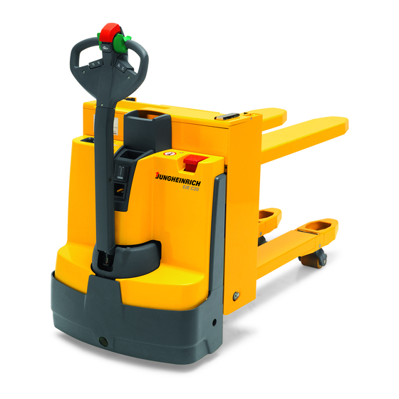
Summary of Contents for Jungheinrich EJE C20
- Page 4 NOTE...
- Page 10 Appendix JH Traction Battery Operating Instructions These operating instructions apply only to Jungheinrich battery models. If using another brand, refer to the manufacturer's operating instructions.
- Page 12 NOTE...
- Page 13 NOTE...
- Page 26 2000 Q max Q max...
- Page 29 Lifting the truck by crane Requirements Tools and Material Required Procedure The truck can now be lifted by crane.
- Page 31 Securing the industrial truck for transport Requirements Tools and Material Required Procedure The truck can now be transported.
- Page 32 NOTE Procedure Truck is operational.
- Page 36 NOTE NOTE...
- Page 37 Requirements Procedure The battery is now exposed.
- Page 38 NOTE Charging the battery Requirements Procedure The battery is charging.
- Page 39 Completing battery charging, restoring the truck to operation NOTE Requirements Procedure The truck is now ready for operation.
- Page 40 NOTE...
- Page 41 Set the charging characteristic Requirements Procedure The charging characteristic is now set. NOTE...
- Page 42 Charging the battery Requirements Procedure The battery is charged. When the mains connector (46) is attached to the mains, all the truck’s electrical functions are disconnected (electric immobilizer). The truck cannot be operated. Completing battery charging, restoring the truck to operation NOTE Requirements Procedure...
- Page 45 Removing the battery Requirements Procedure...
- Page 46 Removing the battery Requirements Procedure The battery is now removed.
- Page 54 NOTE...
- Page 55 Inspection before daily operation Procedure...
- Page 56 Switching on the truck Requirements Procedure The truck is ready for operation.
- Page 57 Procedure...
- Page 58 Park the truck securely Procedure The truck is parked.
- Page 61 Press the Emergency Disconnect switch Procedure All electrical functions are deactivated. The truck brakes to a halt.
- Page 62 Releasing the Emergency Disconnect switch Procedure All electrical functions are enabled and the truck is operational again (provided the truck was operational before the Emergency Disconnect was pressed).
- Page 63 Requirements Procedure The brakes are released and the truck moves in the selected direction.
- Page 64 Changing direction during travel Procedure The truck decelerates until it starts to travel in the opposite direction.
- Page 65 Switch on the slow travel function Procedure The brake is released. The truck travels at slow speed. Switching off slow travel Procedure If the tiller is in brake zone "B", the brake applies and the truck stops. If the tiller is in brake zone "F" the truck continues at slow travel speed.
- Page 66 Procedure The truck is steered in the required direction.
- Page 67 Procedure The truck decelerates at the maximum rate until it comes to a halt. Procedure The truck brakes to a halt regeneratively via the coasting brake. When braking regeneratively, energy is returned to the battery, ensuring a longer service time.
- Page 68 Requirements Procedure NOTE The load handler is raised.
- Page 69 Requirements Procedure The load handler is lowered.
- Page 71 Requirements Procedure The load is being raised. NOTE...
- Page 72 Requirements Procedure...
- Page 73 Requirements Procedure The load is deposited. NOTE...
- Page 75 Activating automatic guidance Requirements...
- Page 77 Requirements Procedure "Automatic lifting" is activated. An optical signal transmitter is actuated to indicate that "automatic lifting" is automatic lift for the operator. The load handler moves to the highest position until the "load" sensors detect the load or the lift limit switch is activated by the load handler. Activating the "load"...
- Page 80 Release the brake Tools and Material Required Procedure The brake is now released. The truck can be moved.
- Page 81 Activating the brake Procedure The brake has been reactivated. The brake is now be applied without current.
- Page 82 GF 60 Operating the truck without its own drive system. Requirements Tools and Material Required Procedure The truck can be moved without its own drive system.
- Page 83 Parking the truck Procedure The brake is now activated again. GF 30...
- Page 86 Preparing the truck for operation by entering a valid operator code Procedure The LED (75) lights up red. When you have entered a valid operator code the LED (75) lights up green, the travel program selected is indicated by the corresponding LEDs (71,72,73) and the truck is switched on.
- Page 87 Requirements Procedure When you enter the valid master code the LED (75) flashes green. The LEDs (71,75) flash green. The LEDs (72,75) flash green. The LEDs (73,75) flash green. Wait until the LED (75) flashes green. The setting is saved. The truck is switched off and the LED (75) is lit red.
- Page 89 Requirements Procedure When you enter the valid master code the LED (75) flashes green. The LEDs (72,75) flash green. The LEDs (73,75) flash green. Wait until the LED (75) flashes green. The setting is saved. The truck is switched off and the LED (75) is lit red. After entering the valid user code the LED (75) lights up green, the travel program setting is shown by the illumination of the corresponding LEDs (71,72,73) and the truck is switched on.
- Page 91 Requirements Procedure When you enter the valid master code the LED (75) flashes green. The LEDs (71,75) flash green. The LEDs (72,75) flash green. The LEDs (73,75) flash green. Wait until the LED (75) flashes green. The setting is saved. The truck is switched off and the LED (75) is lit red.
- Page 93 Requirements Procedure When you enter the valid master code the LED (75) flashes green. The LEDs (72,75) flash green. The LEDs (73,75) flash green. Wait until the LED (75) flashes green. The user code is now deleted. The truck is switched off and the LED (75) is lit red. After entering the user code the LED (75) flashes red and the truck remains switched off.
- Page 95 Requirements Procedure When you enter the valid master code the LED (75) flashes green. The LEDs (73,75) flash green. Wait until the LED (75) flashes green. All user codes are deleted. The truck is switched off and the LED (75) is lit red. After entering the user code the LED (75) flashes red and the truck remains switched off.
- Page 96 Requirements Procedure The length of the new master code is now changed and user codes have been added.
- Page 97 Requirements Procedure When you enter the correct master code the LED (75) flashes green. Wait until the LED (75) flashes green. Wait until the LED (75) flashes green. The setting is saved. The truck is switched off and the LED (75) lights up red. When you have entered a valid operator code the LED (75) lights up green, the travel program selected is indicated by the corresponding LEDs (71,72,73) and the truck is switched on.
- Page 101 Adapting the travel program configuration to the user code Procedure When you enter the valid master code the green LED (75) flashes green. The LEDs (71,75) flash green. The LEDs (72,75) flash green. The LEDs (73,75) flash green. Wait until the LED (75) flashes green. The travel programs are now assigned to the user code.
- Page 105 Acceleration example Procedure The travel parameter is now set.
- Page 106 Checking the settings in programming mode Procedure The truck is now in travel mode and can be checked. Saving travel parameters Requirements Procedure...
- Page 107 Requirements Procedure The "dry maintenance-free" battery type is set. Travel is disabled while the parameters are being entered. Storing the parameter Requirements Procedure The parameter is now saved. Testing an altered parameter Requirements...
- Page 108 Procedure The parameter has now been checked.
- Page 112 NOTE...
- Page 121 Procedure...
- Page 124 Cleaning the truck Requirements Tools and Material Required Procedure The truck is now clean.
- Page 125 Cleaning the electrical system assemblies Requirements Tools and Material Required Procedure The electrical system assemblies are now clean.
- Page 126 Front cover disassembly Requirements Tools and Material Required Procedure The front cover has been removed. Front panel assembly Tools and Material Required Procedure The front panel is now assembled.
- Page 127 Drive panel disassembly Tools and Material Required Procedure The drive panel is now disassembled.
- Page 128 Checking the hydraulic oil level and replenishing Requirements Procedure The hydraulic oil level has now been checked.
- Page 129 Tightening the wheel nuts Requirements Tools and Material Required Procedure The wheel nuts have now been tightened.
- Page 130 Check fuses Requirements Procedure The fuses are now checked.
- Page 131 Procedure...
- Page 132 Procedure NOTE...
- Page 133 Procedure...
- Page 136 NOTE...
- Page 142 NOTE...
- Page 151 Checks and operations to be performed before starting daily work Procedure The test is now complete.
- Page 152 NOTE...
- Page 153 Charging the battery Requirements Procedure The battery is charged. Charging is considered to be complete when the electrolyte density and battery voltage remain constant for more than 2 hours.
- Page 157 Checks and operations to be performed before starting daily work Procedure The test is now complete.
- Page 158 NOTE...
- Page 159 Charging the battery Requirements Procedure The battery is charged. Charging is considered to be complete when the electrolyte density and battery voltage remain constant for more than 2 hours.
- Page 165 NOTE...
- Page 167 Cleaning the battery with a high pressure cleaner Requirements Procedure Battery cleaned.
- Page 168 NOTE...
Need help?
Do you have a question about the EJE C20 and is the answer not in the manual?
Questions and answers