
Subscribe to Our Youtube Channel
Related Manuals for Jungheinrich EJE 114


Summary of Contents for Jungheinrich EJE 114
- Page 1 EJE 114 / 116 / 118 / 120 04.17 Operating instructions en-GB 51564109 07.21 EJE 114 EJE 116 EJE 118 EJE 120...
- Page 3 Declaration of Conformity Manufacturer Jungheinrich AG, 22039 Hamburg, Germany Description Industrial truck Type Option Serial no. Year of manufacture EJE 114 EJE 116 EJE 118 EJE 120 On behalf of Date EU DECLARATION OF CONFORMITY The undersigned hereby declare that the powered truck described in detail complies with the current versions of European Directives 2006/42/EG (Machinery Directive) and 2014/30/EU (Electromagnetic Compatibility - EMC).
- Page 5 Foreword Notes on the operating instructions The present ORIGINAL OPERATING INSTRUCTIONS are designed to provide sufficient instruction for the safe operation of the industrial truck. The information is provided clearly and concisely. The chapters are arranged by letter and the pages are numbered continuously.
- Page 6 Copyright Copyright of these operating instructions remains with JUNGHEINRICH AG. Jungheinrich Aktiengesellschaft Friedrich-Ebert-Damm 129 22047 Hamburg - Germany Tel: +49 (0) 40/6948-0 www.jungheinrich.com...
-
Page 7: Table Of Contents
Contents Correct Use and Application General Correct application Approved application conditions Application area Instructions for trucks with lithium-ion batteries Internal Operation Combined with Brief External or Cold Store Operation (t) Internal Operation in Cold Stores with Cold Store Equipment (o) Proprietor responsibilities Adding attachments and/or accessories Removal of components... - Page 8 Battery types Exposing the battery Battery removal and installation Charging the battery Integrated Modular Lithium-Ion Battery Notes on Lithium-Ion Batteries Safety regulations for handling lithium-ion batteries Battery types Battery data plate Usability as a Function of the Battery Temperature Exposing the battery Charging the battery Operation Safety Regulations for the Operation of Forklift Trucks...
- Page 9 Safety tests to be performed at intervals and after unusual incidents Final de-commissioning, disposal Maintenance, Inspection and Changing of Maintenance Parts Requiring Replacement Maintenance Contents EJE 114/ 116/118/ 120/ 120US Owner Customer Service Maintenance Contents EJE 114 Li-Ion EJE 116 LiIon EJE 118 Li-Ion Owner Customer Service...
-
Page 11: A Correct Use And Application
A Correct Use and Application General The truck must be used, operated and serviced in accordance with the present instructions. All other types of use are beyond its scope of application and may result in damage to personnel, the industrial truck or property. Correct application NOTICE The maximum load and load distance are indicated on the capacity plate and must... -
Page 12: Approved Application Conditions
Approved application conditions Application area WARNING! Use under extreme conditions Using the truck under extreme conditions can result in malfunctions and accidents. uSpecial equipment and authorisation are required if the truck is to be constantly used in extreme conditions, especially in dusty or corrosive atmospheres. uThe truck cannot be used in areas at risk of explosion. -
Page 13: Instructions For Trucks With Lithium-Ion Batteries
Instructions for trucks with lithium-ion batteries WARNING! Danger of accidents due to regenerative braking fault Regenerative braking faults can result in extended stopping distances and accidents, particularly when travelling on inclines. Other persons can be injured in the truck's hazardous area. uKeep all persons out of the hazardous area during travel operations. -
Page 14: Internal Operation Combined With Brief External Or Cold Store Operation (T)
Internal Operation Combined with Brief External or Cold Store Operation (t) In addition to the permissible operating conditions in industrial and commercial environments, the truck can also be used in outdoor environments, cool stores and fresh food areas. Secure parking is only permissible indoors or in a cold store environment. - Page 15 3.3.4 Replaceable Lithium-Ion Battery Usage and ambient conditions Permissible temperature -10 °C to +40 °C range Temperature range for 5 °C to +40 °C secure parking Minimum temperature for +5 °C charging Maximum relative air 95 % non-condensing humidity...
-
Page 16: Internal Operation In Cold Stores With Cold Store Equipment (O)
Internal Operation in Cold Stores with Cold Store Equipment (o) NOTICE Cold store trucks uTrucks designed for use in cold stores have a cold store hydraulic oil and a protective frame instead of a mast guard on the mast. uIf a truck with cold store oil is used outside the cold store, the lowering speeds may increase. -
Page 17: Proprietor Responsibilities
Proprietor responsibilities For the purposes of the present operating instructions the “operating company” is defined as any natural or legal person who either uses the industrial truck himself, or on whose behalf it is used. In special cases (e.g. leasing or renting) the proprietor is considered the person who, in accordance with existing contractual agreements between the owner and user of the industrial truck, is charged with operational duties. -
Page 19: B Truck Description
B Truck Description Application The EJE 114 / 116 / 118 / 120 is designed to transport goods on level surfaces. It can lift open-bottom pallets or pallets with transverse boards outside area the load-wheel area, as well as roll cages. The capacity is shown on the capacity plate, Qmax. -
Page 20: Travel Direction Definition
Travel direction definition The following determinations have been made for travel direction specification: Item Travel Direction Left Drive direction Load direction Right... -
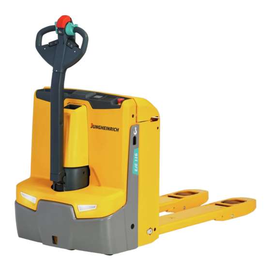
Page 21: Assemblies And Functional Description
Assemblies and Functional Description Assembly Overview The graphic shows the EJE 114 as an example. Item Designation Item Designation t Travel switch o Display unit t Collision safety switch t Key switch o Keypad t "Slow travel" button o Transponder reader/... -
Page 22: Protective And Safety Equipment
Protective and safety equipment Truck contour An enclosed, smooth truck perimeter with rounded edges ensures safe handling of the truck. The wheels are surrounded by a solid skirt offering collision protection. The truck contour must not be changed. Contact the manufacturer’s customer service department, if necessary. -
Page 23: Functional Description
Functional Description Electrical system The truck has an electronic traction controller. The truck electrical system operates with a rated operating voltage of 24 V. Drive system An AC three-phase motor powers the drive wheel via a gearbox. The electronic traction controller ensures smooth speed control of the drive motor and hence smooth starting, powerful acceleration and electrically controlled braking with energy recovery. -
Page 24: Hourmeter
positionCONTROL (o) The "positionCONTROL" option enables comfortable approach of predefined entry and lifted heights and free lift heights for up to three definable pallet types with simple actuation of the raise/lower function. "positionCONTROL" can be activated and deactivated with the display unit menu (o). Before angled entry into a pallet, positionCONTROL must be deactivated as pallets can become damaged in the event of accidental lifting with the automatic function. -
Page 25: Technical Specifications
Technical Specifications Technical data specified in accordance with VDI 2198. Technical modifications and additions reserved. Performance data Designation EJE 114 EJE 116 EJE 118 EJE 120 Rated capacity Q 1400 1600 1800 2000 Travel speed with/without rated 5.0/5.0 6.0/6.0 km/h... -
Page 26: Dimensions
Dimensions Technical data specified in accordance with VDI 2198. Technical modifications and additions reserved. The graphic shows the EJE 114 as an example. a/ 2 a/ 2 As t... - Page 27 Designation EJE 114 EJE 116 EJE 118 EJE 120 h3 Lift Load centre- distance for standard forklength Load handler lowered Tiller height in the travel position min./ 750/1237 max. Wheelbase - / 1252 / 1182 / 1182 / 1252 / 1321...
- Page 28 Side battery removal (SBE): M SBE = L; L SBE = L +53 mm Load section lowered +50 mm Load section lowered +25 mm Battery compartment XS Fixed support wheels...
-
Page 29: Weights
Weights Designation EJE 114 EJE 116 EJE 118 EJE 120 Net weight 280 / 405 / - / 420 / 280 / 420 / 498 / 576 (XS / S / M / L) - / - 498 / 576... -
Page 30: Norms
EN norms Continuous sound pressure level – EJE 114 / 116 / 118 / 120: 61 dB(A) in accordance with EN 12053 as harmonised with ISO 4871. The continuous sound pressure level is calculated according to standard procedures and takes into account the sound pressure level when travelling, lifting and idling. -
Page 31: Specifications According To Red Guideline (Radio Equipment Directive) For Radio Units
Specifications according to RED guideline (Radio Equipment Directive) for radio units The table contains any components installed according to the European Directive 2014/53/EU. The table shows the affected frequency range and the emitted transmission power for each component. Component Frequency range Transmission power WMT 110 13.56 MHz... -
Page 32: Identification Points And Data Plates
Warnings and notices such as capacity charts, strap points and data plates must be legible at all times. Replace if necessary. Indication Points The graphic shows the EJE 114 as an example. Item Designation "Cold store" plate (o) Note on lithium-ion battery (o) -
Page 33: Data Plate
Data plate Item Model Item Model Rated capacity (kg) Load centre distance (mm) Battery voltage (V) Drive output Net weight w.o. battery (kg) Min./max. battery weight (kg) Option Manufacturer Model QR code Serial number Manufacturer's logo Year of manufacture For queries regarding the truck or when ordering spare parts, always quote the truck serial number (32). -
Page 35: C Transport And Commissioning
C Transport and Commissioning Lifting by crane WARNING! All persons involved in loading by crane must be trained Incorrect crane loading procedures due to untrained personnel can cause the truck to fall. There is a risk of injury to personnel and a risk of material damage to the truck. - Page 36 Strap points (40) on the chassis are provided for transporting the truck with crane lifting gear. Lifting the truck by crane Requirements – Park the truck securely, see page 84. Tools and Material Required – Lifting gear – Crane lifting gear Procedure •...
-
Page 37: Transport
Transport WARNING! Uncontrolled movement during transport Improper fastening of the truck and mast during transport can result in serious accidents. uLoading is only to be carried out by specially trained staff. The specialist personnel must be instructed in the securing of loads on road vehicles and in the use of load- securing equipment. -
Page 38: Using The Truck For The First Time
Using the Truck for the First Time WARNING! The use of unsuitable energy sources can be hazardous Rectified AC current will damage the assemblies (controllers, sensors, motors etc.) of the electronic system. Unsuitable cable connections (too long, insufficient wire cross-section) to the battery (tow cables) can overheat, setting the truck and battery on fire. -
Page 39: D Battery - Servicing, Recharging, Replacement
D Battery - Servicing, Recharging, Replacement Notes on Battery Technologies Lead-acid batteries (t) The truck is fitted with a lead-acid battery as standard. The associated descriptions are in the chapter titled "Replaceable lead-acid and lithium-ion batteries" – see page 40. Replaceable lithium-ion batteries (o) The truck is optionally fitted with a replaceable lithium- ion battery. -
Page 40: Replaceable Lead-Acid And Lithium-Ion Batteries
The use of unsuitable batteries that have not been approved for the truck by Jungheinrich, can lead to a deterioration of the braking characteristics of the truck during energy recovery, causing considerable damage to the electric controller and resulting in serious danger to the health and safety of individuals. - Page 41 WARNING! Risk of accidents and injuries when handling acid batteries Batteries contain dissolved acid, which is toxic and caustic. Above all, avoid any contact with battery acid. uDispose of used battery acid in accordance with regulations. uAlways wear protective clothing and eye protection when working with batteries. uDo not let battery acid come into contact with skin, clothing or eyes.
-
Page 42: Battery Types
(mm) 25.7 V Li-ion 40 Ah 17.5 531 x 72 x 421 EJE 114 / 116 / 118 with 40 Ah battery switch off automatically after 5 minutes to save energy. Battery tray S (top battery removal) Battery dimensions Voltage... - Page 43 Battery tray M (side battery removal) Battery dimensions Voltage Battery type Weight (kg) (mm) 2PzV 160 Ah 2PzS 180 Ah 624 x 212 x 537 2PZV 174 Ah 2PzM 180 Ah 2PzV 200 Ah 2PzS 250 Ah 24 V 2PZV 220 Ah 2PzM 250 Ah 624 x 212 x 628 XFC 158 Ah...
-
Page 44: Exposing The Battery
Exposing the battery Battery compartment S, M, L Battery compartment XS Requirements – Truck parked securely on a horizontal surface, see page 84. Procedure • Open the battery panel (8). The battery is now exposed. -
Page 45: Battery Removal And Installation
Battery removal and installation WARNING! Accident risk during battery removal and installation Due to the battery weight and acid there is a risk of trapping or scalding when the battery is removed and installed. uNote the "Safety regulations for handling acid batteries" section in this chapter. uWear safety shoes when removing and installing the battery. - Page 46 2.4.1 Removing the battery from the top Battery compartment XS Removing the case battery Requirements – The truck is parked securely – see page 84. – The battery lid is opened – see page 44. Procedure • Pull the case battery (42) to the left without tilting the battery. This disconnects the battery connector (44) from the truck connector.
- Page 47 Installing the case battery Procedure • Insert the case battery (42) into the battery compartment from above. • Push the case battery to the right as far as the stop. • Close the battery lid. Closing the battery panel interlocks the case battery and the battery connector (44) is firmly connected to the truck connector.
- Page 48 Battery compartment S, M, L Removing the battery Requirements – Truck parked securely – see page 84. – Battery exposed – see page 44. Tools and Material Required – Crane lifting gear Procedure • Disconnect the battery connector from the truck connector. Place the battery cable on the battery tray so that it cannot be severed when the battery is extracted.
- Page 49 2.4.2 Removing the battery from the side CAUTION! Trapping hazard Trapping hazard when removing and installing the battery. uWhen removing and installing the battery do not put your hands between the battery and the chassis. Removing the battery Requirements – The truck is parked securely, see page 84. –...
- Page 50 The battery is now installed. After each replacement, check that the battery is properly secured by the battery lock.
-
Page 51: Charging The Battery
Charging the battery 2.5.1 Safety Information There is information on charging the replaceable lithium-ion batteries in the separate operating instructions. Information on charging integrated modular lithium-ion batteries – see page 69. WARNING! Risk of electric shock and fire due to lacking or inappropriate residual current devices A lack of residual current devices or the use of inappropriate residual current devices can result in fatal injury due to electric shocks or electrical fires in the event of a fault. - Page 52 Charging a battery that is not suitable for this charger can result in damage to the charger and battery. The battery could expand or burst. uThe lithium ion battery must only be charged with the Jungheinrich charger designed for this battery.
- Page 53 If the battery is deeply discharged or if the battery temperature is below the permissible level (+5 °C), the battery will not charge. Deeply discharged batteries cannot be charged by the operator (faulty). Contact the manufacturer's customer service department. Charging the battery Requirements –...
- Page 54 Battery compartment S, M, L Requirements – The truck is parked securely, see page 84. – Battery exposed, see page 44. – The charging program that matches the battery type is set on the battery charger. Procedure • Remove the insulating mat from the battery, if present. •...
- Page 55 Complete battery charging and restore the truck to operation Requirements – Battery charging is complete. Procedure • Switch off the charger. • Remove the battery connector (48) from the charging cable (49). • Connect the battery connector (48) to the truck. •...
- Page 56 2.5.3 Charging the battery with the on-board charger 2.5.3.1 Safety Information DANGER! Risk of electric shock and fire Damaged and unsuitable cables can cause electric shocks and can overheat, resulting in fires. uAlways use mains cables with a maximum length of 30 m. Local regulations must be observed.
- Page 57 2.5.3.3 Starting Charging Mains connection of the on-board charger Component Mains voltage Mains frequency 230 V 50 - 60 Hz ELH on-board charger (o) (+15 %, -10 %) (+15 %, -10 %) The mains cable and mains connector (50) of the on-board charger are stowed in a storage compartment in the front panel (14).
- Page 58 Completing battery charging; restoring the truck to operation Requirements – Battery is charged. Procedure NOTICE Cable damage due to pulling If the mains connector is pulled out of the socket from the cable, the cable may be damaged. uDo not pull from the cable. uTake hold of the mains connector and pull out of the mains socket.
- Page 59 Charge status Battery compartment XS with display unit (2-inch display) Item Control or display Function element Battery capacity display Battery discharge status Further information on the 2-inch display under optional equipment – see page 104.
- Page 60 LED display (52) Green LED (charge status) Charging complete, battery full. (Pause in charging, trickle charge or compensation charging). Slow flash Charging. Rapid flash Displayed when a charge begins or after setting a new characteristic curve. Number of flash pulses corresponds to the characteristic curve set.
-
Page 61: Integrated Modular Lithium-Ion Battery
The truck is optionally fitted with an integrated modular lithium-ion battery. All notes and information concerning lithium-ion batteries can be found in these operating instructions. The Jungheinrich lithium-ion batteries are maintenance-free batteries with rechargeable high-performance energy cells. The batteries' daily operating time can be extended through intermediate charges. -
Page 62: Safety Regulations For Handling Lithium-Ion Batteries
The information in these operating instructions regarding the operating conditions and handling instructions, in particular the use of the battery charger provided by Jungheinrich, must be strictly complied with without exception. If the lithium-ion battery is used as intended, no special measures are required, see page 11. - Page 63 3.2.3 Touch voltage hazard WARNING! Risk of accident due to contact voltage Hazardous contact voltages may occur in the event of a technical or mechanical defect on the battery. This may also be the case on an apparently discharged battery. uTag out the faulty battery and take out of service.
- Page 64 3.2.6 Shipping information The Jungheinrich lithium-ion battery is a hazardous material. The applicable ADR regulations must be observed during transport. ADR = Accord européen relatif au transport international des marchandises Dangereuses par Route. If in doubt, contact the manufacturer's customer service department.
- Page 65 IATA classification (air UN 3480 lithium-ion battery class 9 transport) - Danger label UN 3480 LITHIUM-IONEN-BATTERIEN Exposure scenario Not specified. Substance safety rating Not specified. Product does not require marking under EC Directive / Marking HazMatR. 3.2.6.2 Shipping faulty batteries To transport these faulty lithium-ion batteries, contact the manufacturer's customer service department.
-
Page 66: Battery Types
3.2.8 Instructions for disposal NOTICE Lithium-ion batteries must be disposed of in accordance with the relevant national environmental protection regulations. uFor lithium-ion battery disposal, contact the manufacturer's customer service department. Used lithium-ion batteries are recyclable commodities. These batteries must be treated as hazardous waste. -
Page 67: Battery Data Plate
Battery data plate The integrated modular lithium-ion battery is an inherent component of the truck and must not be changed by the operator or owner. For this reason, the data plate of the battery is not directly visible. Lithium Ion Secondary Battery / Lithium Ionen Sekundärbatterie Type Year of Manufacture Baujahr... - Page 68 3.4.1 Safety and warning information Used lithium-ion batteries must be treated as hazardous waste. Lithium-ion batteries marked with the recycling symbol and the sign showing a crossed-out waste bin must not be disposed of with ordinary household waste. Buy-back terms and type of recycling are to be agreed with the manufacturer in example to accordance with the Battery Directive 2006/66/EG, for example.
-
Page 69: Usability As A Function Of The Battery Temperature
Usability as a Function of the Battery Temperature Lithium-ion battery Usability temperature Travel and hydraulic functions: -10 °C to +55 °C 1), 2) – The usable battery capacity and power are reduced at low temperatures. Charging of the lithium-ion battery: –... - Page 70 Only charge the lithium-ion battery with the manufacturer's stationary battery charger SLH 300i. Observe the battery charger operating instructions. WARNING! Warning: hazardous electrical voltage! The charger is an electric component conducting voltages and currents that are hazardous to people. uThe charger must only be operated by trained technicians. uDisconnect the mains supply and the battery connector before carrying out any work on the charger.
- Page 71 WARNING! Danger of overheating when charging with an unsuitable battery charger The use of an unsuitable charger can cause the battery to overheat. uOnly charge the lithium-ion battery with a battery charger specially designed for this battery. Observe the operating instructions and operating conditions for the battery charger.
- Page 72 3.7.5 Trickle charging the lithium-ion battery A fully charged lithium-ion battery can be connected to the battery charger for automatic trickle charging. In the event of an extended period out of use, it is recommend that the trickle charge function of the battery charger be used in order to maintain the available capacity of the battery.
- Page 73 3.7.6 Charging the battery with a stationary charger Only charge the lithium-ion battery with the manufacturer's stationary battery charger SLH 300i. Observe the battery charger operating instructions. Charging the battery Requirements – The truck is parked securely, see page 84. –...
- Page 74 WARNING! There is a danger of sparks if charging is improperly interrupted Owing to the high charge currents, there is a risk of spark discharge if the charge connector is removed while charging is active. There is a risk of injury and of damage to the electrical contacts.
-
Page 75: E Operation
E Operation Safety Regulations for the Operation of Forklift Trucks Driver authorisation The truck may only be used by suitably trained personnel, who have demonstrated to the proprietor or his representative that they can drive and handle loads and have been authorised to operate the truck by the proprietor or his representative. -
Page 76: Displays And Controls
Displays and Controls... - Page 77 Item Controls and displays Function Travel switch t Controls travel direction and speed. t Safety feature Collision safety switch When the collision safety switch is actuated, the truck travels for approx. 3 seconds in the fork direction. The parking brake then applies.
- Page 78 Item Controls and displays Function t Activates an audible signal. "Warning signal" button o Replaces the key switch Transponder reader Transponder reader Plus – Solely to expand the display unit – Releases the truck via a card/ transponder o Replaces the key switch Keypad –...
-
Page 79: Charge Status Indicator
Charge Status Indicator After the truck has been started, the charge status of the battery is shown. The LED (77) colours represent the following conditions: LED colour Charge status Green 40 - 100% Orange 30 - 40 % Green/orange 20 - 30 % flashes 1 Hz 0 - 20 % If the LED is lit red, load can no longer be lifted. -
Page 80: Starting Up The Truck
Starting up the truck Checks and operations to be performed before starting daily operation WARNING! Any damage and other defects to the truck can result in accidents. If damage or other truck defects are discovered during the following checks, the truck must be taken out of service until it has been repaired. -
Page 81: Preparing The Truck For Operation
Preparing the truck for operation Item Description Transponder reader Plus (EasyAccess Transponder): – Only in combination with the display unit (81) – Up to 100 transponders can be stored Transponder reader (EasyAccess Transponder): – Only in combination with the display unit (81) –... - Page 82 Switching on the truck Requirements – Checks and operations before starting daily work completed, see page 80. Procedure • Make sure that the emergency disconnect switch (10) is unlocked. • Switch on the truck; to do this • Insert the key into the key switch (82) and turn it as far to the right as it will go. •...
-
Page 83: Checks And Operations To Be Carried Out When The Truck Is Operational
Checks and operations to be carried out when the truck is operational WARNING! Risk of accident due to damage to or other defects in the truck and optional features If damage or other truck or attachment (optional equipment) defects are discovered during the following checks, the truck must be taken out of service until it has been repaired. -
Page 84: Parking The Truck Securely
Parking the truck securely WARNING! An unsecured truck can cause accidents Do not leave an unsecured truck. uPark the truck securely when leaving it. uException: If the operator intends to remain in the immediate vicinity and is leaving the truck for only a short while, the applied parking brake is sufficient to hold the truck, see page 94. - Page 85 Parking the truck securely Procedure • Park the truck on a level surface. • Fully lower the load handler (85) – see page 95. • Set the drive wheel to "straight-ahead travel" using the tiller (9). • Switch off the truck; to do this: •...
-
Page 86: Industrial Truck Operation
Industrial Truck Operation Safety regulations for truck operation Travel routes and work areas Only use lanes and routes specifically designated for traffic. Unauthorised third parties must stay away from work areas. The load may only be stored in the designated locations. The truck must only be operated in work areas with sufficient lighting to avoid danger to personnel and materials. - Page 87 Negotiating slopes and inclines When negotiating slopes and inclines, observe the following: – Negotiating slopes and inclines in accordance with the technical specifications is permissible only if they are marked as traffic lanes. – Before negotiating slopes, ensure that the truck has sufficient gradeability – see page 25.
- Page 88 Faults due to strong magnets WARNING! Electromagnetic influence can result in accidents Strong magnets can cause electronic components such as Hall sensors to become damaged, resulting in accidents. uDo not use magnets in the operating area of the truck. Exceptions to this rule are commercial, weak clamping magnets for attaching notices.
-
Page 89: Emergency Disconnect
Emergency Disconnect CAUTION! Applying maximum braking can result in accidents Applying the Emergency Disconnect switch during travel will cause the truck to decelerate to a halt at maximum force. This may cause the load to slide off the load handler. There is a higher risk of accidents and injury. uDo not use the Emergency Disconnect switch as a service brake. -
Page 90: Automatic Braking
Automatic braking When the tiller is released, it returns automatically to the upper brake zone (B) and the brakes are applied automatically. WARNING! Risk of collision due to a defective tiller Operating the truck with a defective tiller can lead to collisions with persons or objects. -
Page 91: Travel
Travel WARNING! Risk of collision due to faulty travel switch Operating the truck with a faulty travel switch can result in collisions with other people and objects. uIf the travel switch returns to the neutral position too slowly or not at all when released, the truck must be taken out of service until the cause of this fault is identified and rectified. -
Page 92: Changing Direction During Travel
Changing direction during travel CAUTION! Danger when changing direction during travel Changing direction during travel causes the truck to decelerate sharply. When the truck changes direction, it can start travelling at high speed in the opposite direction unless the travel switch is released in time. uAfter setting off in the opposite direction, apply the travel switch gently or not at all. -
Page 93: Slow Travel
Slow travel CAUTION! The driver must be particularly careful when applying the “slow travel” button (7). The brake is only activated when the "slow travel" button is released. uIn hazardous situations, brake by immediately releasing the slow travel button (7) or the travel switch (5). -
Page 94: Brakes
The truck is steered in the required direction. Brakes CAUTION! uIn hazardous situations, swing the tiller to the brake position or press the emergency disconnect switch. Braking types The brake pattern of the truck depends largely on the travel-lane conditions. The driver must take this into account when driving the truck. -
Page 95: Lifting, Transporting And Depositing Loads
Regenerative braking Procedure • If the travel switch is set to 0, the truck automatically brakes regeneratively. The truck brakes to a halt regeneratively via the coasting brake. The brake is then applied. When braking regeneratively, energy is returned to the battery, ensuring a longer service time. - Page 96 Picking up the load Requirements – Load is correctly palletised. – Load weight matches the truck's capacity. – Forks evenly loaded for heavy loads. Procedure • Drive the truck carefully up to the pallet. • Carefully insert the fork arms into the pallet. •...
- Page 97 Lift cut-out The EJE 114 / 116 / 118 / 120 is optionally equipped with automatic lift cut-off. This function can be set by the operator when needed. For this, the truck must be secured and parked without load. The "Lift" button (88) is then pressed for approx.
- Page 98 4.9.1 Lifting or lowering the load handler with the automatic lifting/lowering function - positionCONTROL (o) WARNING! Risk of accidents while lifting with the automatic lifting function Damage can occur from the use of the automatic lifting function in the hazardous area of the truck, since this function cannot be cancelled by releasing a control.
- Page 99 Requirements – Truck operational, see page 81. Procedure • Briefly actuate the "lift" button (88). The load handler is raised continuously up to the free lift height. Procedure • Briefly actuate the "lower" button (87). The load handler is lowered continuously down to the lifted height or the lowering limit.
-
Page 100: Troubleshooting
Troubleshooting This chapter enables the operator to localize and rectify basic faults or the results of incorrect operation himself. When trying to locate a fault, proceed in the order shown in the remedy table. If, after carrying out the following remedial action, the truck cannot be restored to operation or if a fault in the electronics system is displayed with a corresponding error code, contact the manufacturer’s service department. -
Page 101: Lithium-Ion Battery Fault
Lithium-ion battery fault If any faults are found in the battery or the Jungheinrich charger, contact the manufacturer's customer service department immediately. The operating company must not carry out any remedial work on its own. Independent attempts to tamper with or repair the battery may invalidate the warranty. - Page 102 5.3.2 Truck can no longer be switched on Event message Possible cause Actions The lithium-ion battery – Charge the battery, has switched to energy- see page 69 saving mode to protect – If the problem against deep discharge persists, contact the manufacturer's customer service department...
-
Page 103: Operating The Truck Without Its Own Drive System
Operating the truck without its own drive system WARNING! Accidental truck movement When the brakes are deactivated, the truck must be parked on a level surface, as the brakes are no longer effective. uDo not install or remove the brake on slopes or inclines. uThe brake may only be installed or removed by the manufacturer's customer service department. -
Page 104: Optional Equipment
Optional equipment Display unit (2 inch display) Item Control or Function display Information line Display of event messages, speed and remaining run time Battery capacity display Battery discharge status Symbol field Displays the symbols, see page 107. Battery type Displays the set battery type or set battery (characteristics) characteristic curve 1 = Maintenance-free gel/dry-cell battery... - Page 105 7.1.1 Information field Any event messages are shown in the left section of the information line (89). The right section of the information line shows the truck speed in km/h or mph. 7.1.2 Button Allocation of the Display Unit (o) Functions and operator menus that can be operated via the icons and keys of the display unit depend on the operating situation as well as the scope and settings of the truck.
- Page 106 Key allocation in menu for managing codes or transponders (o) Symbol Meaning Change Set-Up Code: To change the set-up code and to activate the keypad or the transponder reader. Edit access code / transponder: To add or delete access codes and transponders. Up selection: To select access codes or transponders.
- Page 107 7.1.3 Symbols in the display Any number of pictograms can be displayed in the pictogram field (90). Which pictograms are shown in the pictogram field depends on the operating and truck status. Symbol Meaning Colour Function Emergency stop Lights up in the case of automatic function deactivation due to truck malfunctions.
- Page 108 Symbol Meaning Colour Function Lift limit, support Yellow Illuminates if the “Raise support arm arm lift lift” button is pressed when the lift limit in the support arm lift has been reached. Lowering limit, Yellow Illuminates if the “Lower support arm support arm lift lift”...
-
Page 109: Emergency Operation With Service Key Gf60 (O)
Emergency Operation with Service Key GF60 (o) The GF60 service key must not remain on the truck during normal operation. The service key may only be used by an authorised person. WARNING! Accidental truck movement When the brakes are released, the truck must be parked securely on a level surface, since the brakes are no longer effective. - Page 110 Parking the truck Procedure • Turn the service key to the 0 position and remove the key. After switching back from level 2 to level 1, the lock bar returns to its original position. The brake is now activated again. WARNING! Only return the truck to service when you have identified and rectified the fault.
-
Page 111: Keyless Access System
Keyless Access System The keyless access systems serve as a replacement for the key switch to release the truck. The keyless access system allows an individual code to be allocated to each operator or group of operators. Item Description Transponder reader Plus (EasyAccess Transponder): –... -
Page 112: General Information About The Use Of Keyless Access Systems
General Information about the Use of Keyless Access Systems The default code is to be found on a sticker. When using for the first time, change the set-up code and remove the sticker! – Default code: 1-2-3-4 – Factory set-up code: 2-4-1-2 When allocating the codes, ensure the rider trucks are given a different code than pedestrian trucks. - Page 113 7.5.1 Activating the keypad Procedure • Release emergency disconnect switch, see page 89. • Enter the default code 1-2-3-4 using the keys below the display unit (81). The truck is switched on. • Press the key below the "Settings" symbol (98). •...
- Page 114 7.5.2 Activating the transponder reader Procedure • Release emergency disconnect switch, see page 89. • Enter the default code 1-2-3-4 using the keys below the display unit (81). The truck is switched on. • Press the key below the "Settings" symbol (98).
-
Page 115: Using The Display
Using the Display: 7.6.1 Switch on the truck with the access code. Procedure • Release emergency disconnect switch, see page 89. • Enter the access code with the buttons below the display (81). The truck is switched on. 7.6.2 Switching off the truck Procedure •... - Page 116 7.6.3 Changing the Set-up Code Requirements – The truck is switched on, see page 120. Procedure • Press the key below the "Settings" symbol (98). • Press the key below the "Change set- up code" symbol (99). • Enter the set-up code using the keys below the display unit (81).
- Page 117 7.6.4 Adding a new access code Requirements – The truck is switched on, see page 120. Procedure • Press the key below the "Settings" symbol (98). • Press the key below the "Edit access code" symbol (104). The set-up code is requested. •...
- Page 118 7.6.5 Deleting an access code Requirements – The truck is switched on, see page 120. Procedure • Press the key below the "Settings" symbol (98). • Press the key below the "Edit access code" symbol (104). The set-up code is requested. •...
- Page 119 7.6.6 Displaying the Log-in Process The use of the last different access codes is displayed during the log-in process. The last log-in is displayed first. If multiple access codes are logged as being displayable simultaneously, the display area can be moved by scrolling forward or back. Requirements –...
-
Page 120: Using The Keypad
Using the Keypad 7.7.1 Switch on the truck with the access code. Procedure • Release the emergency disconnect switch, see page 89. • Enter the access code with the keypad (80). The truck is switched on. Procedure • Press the key under the "Switch off" symbol (103) in the display unit. •... - Page 121 7.7.3 Changing the Set-up Code Requirements – The truck is switched on, see page 120. Procedure • Press the key below the "Settings" symbol (98). • Press the key below the "Change set- up code" symbol (99). • Enter the set-up code using the keypad (80).
- Page 122 7.7.4 Adding a new access code Requirements – The truck is switched on, see page 120. Procedure • Press the key below the "Settings" symbol (98). • Press the key below the "Edit access code" symbol (104). The set-up code is requested. •...
- Page 123 7.7.5 Deleting an access code Requirements – The truck is switched on, see page 120. Procedure • Press the key below the "Settings" symbol (98). • Press the key below the "Edit access code" symbol (104). The set-up code is requested. •...
- Page 124 7.7.6 Displaying the Log-in Process The use of the last different access codes is displayed during the log-in process. The last log-in is displayed first. If multiple access codes are logged as being displayable simultaneously, the display area can be moved by scrolling forward or back. Requirements –...
-
Page 125: Operating The Transponder Reader
Operating the transponder reader NOTICE Take care not to damage the transponder. If the transponder is damaged, the truck cannot be switched on. 7.8.1 Switching on the truck with the transponder Procedure • Release the Emergency Disconnect switch, see page 89. •... - Page 126 7.8.3 Changing the Set-up Transponder Requirements – The truck is switched on, see page 125. Procedure • Press the key below the "Settings" symbol (98). • Press the key below the "Change set-up code" symbol (99). • Place the set-up transponder on the transponder reader (79).
- Page 127 7.8.4 Adding a new transponder Requirements – The truck is switched on, see page 125. Procedure • Press the key below the "Settings" symbol (98). • Press below "Edit transponder" symbol (104). The set-up transponder is requested. • Place the set-up transponder on the transponder reader (79).
- Page 128 7.8.5 Deleting transponders Requirements – The truck is switched on, see page 125. Procedure • Press the key below the "Settings" symbol (98). • Press the key below the "Edit transponder" symbol (104). set-up transponder requested. • Place the set-up transponder on the transponder reader (79).
- Page 129 7.8.6 Displaying the Log-in Process The use of the last different transponders is displayed during the log-in process. The last log-in is displayed first. If multiple transponders are logged as being displayable simultaneously, the display area can be moved by scrolling forward or back. Requirements –...
-
Page 130: Fleet Management System
Fleet Management System If equipped with a Jungheinrich fleet management component, see the "Jungheinrich fleet management system" operating instructions. 7.10 Parameters The default settings can be changed by the manufacturer's customer service department. For supplied batteries, the correct battery parameter is set ex works. -
Page 131: Truck Maintenance
(www.jungheinrich.de/spare-parts-search) by entering the serial number. The serial number can be found on the data plate, see page 33. Operational Safety and Environmental Protection The inspections and maintenance tasks listed in chapter "Maintenance, Inspection and Changing of Maintenance Parts Requiring Replacement" must be performed according to the defined service intervals (see page 151). - Page 132 Exception: Operating companies should only make changes or have changes made to powered industrial trucks if the manufacturer is no longer operating in the field and there is no successor to the business; operating companies must however: – Ensure that the changes to be made are planned, tested and performed by a specialist engineer in industrial trucks taking safety into account.
-
Page 133: Maintenance Safety Regulations
Maintenance Safety Regulations Maintenance personnel The truck should only be serviced and repaired by the manufacturer's specialist customer service personnel who have been trained to do this. We therefore recommend that you enter into a maintenance contract with the manufacturer’s local sales office. -
Page 134: Consumables And Used Parts
Consumables and used parts CAUTION! Consumables and used parts are an environmental hazard Used parts and consumables must be disposed of in accordance with the applicable environmental-protection regulations. Oil changes should be carried out by the manufacturer's customer service department, whose staff are specially trained for this task. - Page 135 NOTICE Testing and replacing hydraulic hoses Hydraulic hoses can become brittle through age and must be checked at regular intervals. The operating conditions of the truck have a considerable impact on the ageing of the hydraulic hoses. uHydraulic hoses must be checked at least 1x per year and replaced if necessary. uIf the operating conditions become more arduous, the inspection intervals must be reduced accordingly.
-
Page 136: Lubricants And Lubrication Schedule
Lubricants and Lubrication Schedule Handling consumables safely Handling consumables Consumables must always be handled correctly. Follow the manufacturer’s instructions. WARNING! Improper handling is hazardous to health, life and the environment Consumables can be flammable. uKeep consumables away from hot components and naked flames. uAlways keep consumables in prescribed marked containers. - Page 137 CAUTION! Consumables and used parts are an environmental hazard Used parts and consumables must be disposed of in accordance with the applicable environmental-protection regulations. Oil changes should be carried out by the manufacturer's customer service department, whose staff are specially trained for this task.
-
Page 138: Lubrication Schedule
Lubrication Schedule The truck is equipped with lubrication-free bushes. As such, no lubrication is required as part of maintenance. k Cold store application Hydraulic-oil filler plug b Transmission oil filling... -
Page 139: Consumables
1:1 ratio. *The trucks are factory-equipped with a special hydraulic oil (the Jungheinrich hydraulic oil with a blue colouration) and the cold store hydraulic oil (red colouration). The Jungheinrich hydraulic oil is available only from the Jungheinrich service department. The Jungheinrich hydraulic... -
Page 140: Maintenance And Repairs
Maintenance and repairs Preparing the truck for maintenance and repairs Procedure • Park the truck securely, see page 84. • Disconnect the battery to prevent the truck from being switched on accidentally. Lifting and jacking up the truck safely WARNING! Lifting and jacking up the truck safely In order to raise the truck, the lifting gear must only be secured to the points specially provided for this purpose. -
Page 141: Front Panel Disassembly And Assembly
Front panel disassembly and assembly Removing the covers Requirements – Truck prepared for maintenance and repair work, see page 140. Tools and Material Required – Allen key, size 13 (7 Nm) Procedure • Remove the M8 hex. bolt with width across flats 13 (7 Nm) (109) from the front panel (14). -
Page 142: Cleaning
Cleaning 5.4.1 Cleaning the truck Cleaning tasks may only take place in the designated locations, which adhere to the stipulations of the country of use. CAUTION! Risk of fire due to use of flammable cleaning agents Using flammable cleaning agents increases the risk of fire. uDo not use any flammable cleaning agents when cleaning. - Page 143 5.4.2 Cleaning the electrical system assemblies NOTICE Risk of electrical-system damage Cleaning the electronic system assemblies (controllers, sensors, motors etc.) with water can damage the electrical system. uDo not clean the electrical system with water. uClean the electrical system with weak suction or compressed air (use a compressor with a water trap) and a non-conductive, anti-static brush.
-
Page 144: Check Wheel Attachment And Wear
Check wheel attachment and wear Replace the wheels if the wear limit (114) has been reached. The drive wheel must only be replaced by authorised service personnel. The wheel nuts on the drive wheel must be re-tightened in accordance with the maintenance intervals indicated in the maintenance checklist, see page 151. -
Page 145: Checking The Hydraulic Oil Level
Checking the hydraulic oil level Checking the oil level Requirements – Lower the load handler. – Prepare the truck for maintenance and repairs, see page 140. Procedure • Disassemble the front panel, see page 141. • Check the oil level in the hydraulic reservoir (116). With the load handler lowered, the hydraulic oil level in the hydraulic reservoir must be at roughly the "... -
Page 146: Check The Distance Of The Fixed Support Wheels
Check the distance of the fixed support wheels On trucks with fixed support wheels, the distance between level ground and fixed support wheels must always be more than 2 mm. If necessary, the height of the support wheels must be adjusted. Four different insertion positions are provided for this purpose. -
Page 147: Checking Electrical Fuses
Checking electrical fuses Checking fuses Requirements – Truck prepared for maintenance and repair work, see page 140. – Front panel removed, see page 141. Procedure • Check the fuse ratings against the table and their condition, and replace if necessary. The fuses have been checked. -
Page 148: Restoring The Truck To Service After Maintenance And Repairs
Restoring the truck to service after maintenance and repairs Procedure • Thoroughly clean the truck – see page 142. • Lubricate the forklift truck according to the lubrication schedule – see page 138. • Equipped with lead-acid battery (t): Clean the battery, grease the battery terminal screws with terminal grease and connect the battery. -
Page 149: Decommissioning The Industrial Truck
Decommissioning the industrial truck If the truck is to be out of service for more than a month, it must be stored in a frost- free and dry room. All necessary measures must be taken before, during and after decommissioning as described hereafter. When the truck is out of service it must be jacked up so that all the wheels are clear of the ground. -
Page 150: Restoring The Truck To Service After Decommissioning
Restoring the truck to service after decommissioning Procedure • Thoroughly clean the truck – see page 142. • Lubricate the forklift truck according to the lubrication schedule – see page 138. • Equipped with lead-acid battery (t): Clean the battery, grease the battery terminal screws with terminal grease and connect the battery. -
Page 151: Maintenance, Inspection And Changing Of Maintenance Parts Requiring Replacement
G Maintenance, Inspection and Changing of Maintenance Parts Requiring Replacement WARNING! Lack of maintenance can result in accidents Failure to perform regular maintenance and inspections can lead to truck failure and poses a potential hazard to personnel and equipment. uThorough and expert maintenance and inspections are among the most important requirements for the safe operation of the industrial truck. -
Page 152: Maintenance Contents Eje 114/ 116/118/ 120/ 120Us
Maintenance Contents EJE 114/ 116/118/ 120/ 120US Issued on: 2021-06-14 08:00 Owner To be performed every 50 service hours, but at least once a week. 1.1.1 Maintenance contents 1.1.1.1 Standard equipment Hydraulic operations Correct the hydraulic-oil level. Steering Test the tiller return function. -
Page 153: Customer Service
Lead-acid battery Power supply Check the battery cable connections for secure attachment Customer Service In accordance with the EJE 114/ 116/118/ 120/ 120US service interval, to be performed every 1000 service hours, but at least once a year. 1.2.1 Maintenance contents 1.2.1.1... - Page 154 Electrical system Test the contactors and/or relays. Carry out a frame leakage test. Chassis/structure Check that the panels and covers as well as mounting brackets are secure. Ensure they function correctly and are safe. Hydraulic operations Correct the hydraulic-oil level. Test the pressure relief valve.
- Page 155 Lead-acid battery, international Electrical system Carry out a frame leakage test. Power supply Clean the battery. Clean and grease the battery terminals. Measure acid density and battery voltage. Correct the battery-acid level using demineralised water. Lead-acid battery Electrical system Carry out a frame leakage test. Power supply Clean the battery.
- Page 156 Chassis/structure Industrial truck for damage and leaks Check chassis connections and screw connections are securely attached and check for damage Check labels for legibility, completeness and plausibility Mechanism to protect against trapping and shearing is present, secure, functions correctly and is free of dirt and damage Hydraulic operations Test hydraulic controls and check their labels for legibility, completeness and plausibility Lift mechanism for wear, functionality and damage...
- Page 157 Shock sensor/data recorder Electrical system Check shock sensor/data recorder is securely attached and check for damage Radio data System components Scanner and terminal for secure fit, functionality and damage Fuses for correct ratings Check cables are securely attached and check for damage Access module Electrical system Check access module is securely attached, test and check for damage...
- Page 158 1.2.3.1 Standard equipment maintenance part service hours months Gear oil 10000 Hydraulic system breather filter 2000 Hydraulic oil 2000 Hydraulic oil filter 2000 1.2.3.2 Optional equipment Cold store application maintenance part service hours months Transmission oil in cold store application Hydraulic oil Hydraulic oil additive...
-
Page 159: Maintenance Contents Eje 114 Li-Ion Eje 116 Liion Eje 118 Li-Ion
Maintenance Contents EJE 114 Li-Ion EJE 116 LiIon EJE 118 Li-Ion Issued on: 2021-06-29 11:00 Owner To be performed every 50 service hours, but at least once a week. 2.1.1 Maintenance contents 2.1.1.1 Standard equipment Brakes Test the brake. Hydraulic operations Correct the hydraulic-oil level. -
Page 160: Customer Service
Optional equipment The following points must be checked: Customer Service In accordance with the EJE 114 Li-Ion EJE 116 LiIon EJE 118 Li-Ion service interval, to be performed every service hours, but at least once a year. 2.2.1 Maintenance contents 2.2.1.1... - Page 161 2.2.1.2 Optional equipment Radio data System components Clean the scanner and terminal. 2.2.2 Inspection contents The following points must be checked: 2.2.2.1 Standard equipment Electrical system Cables and motor for secure fit and damage Warning and safety equipment in accordance with the operating instructions Functionality of display and controls Test emergency disconnect switch and check for damage Check electrical wiring for damage (insulation damage, connections) and check whether...
- Page 162 Hydraulic operations Test hydraulic controls and check their labels for legibility, completeness and plausibility Lift mechanism for wear, functionality and damage Check cylinders and piston rods are securely attached and check for damage Test hydraulic system Check fork arms or load handler for wear and damage Tie/plunger rods for uniform adjustment, wear and damage Check the hoses, pipes and connections are securely attached and check for wear, leaks, damage, blisters and kinks...
- Page 163 2.2.3.1 Standard equipment maintenance part service hours months Gear oil 10000 Hydraulic system breather filter 2000 Hydraulic oil 2000 Hydraulic system – venting plug 2000...
Need help?
Do you have a question about the EJE 114 and is the answer not in the manual?
Questions and answers
The truck has an alarm when moving. A recent technician fix, also changed the moving alarm to one that is far louder and sounds like a firealarm. Previously it was a beeeeeep beeeeep. Which dint make people think somone had run out of a fire escape. How do we change the movement alarm to the one we are used to ?