Table of Contents
Advertisement
Advertisement
Table of Contents

Related Manuals for Jungheinrich EFX 413


Summary of Contents for Jungheinrich EFX 413
- Page 1 EFX 410 / 413 03.13 Operating instructions en-GB 51296679 04.19 EFX 410 EFX 413...
- Page 3 Declaration of Conformity Manufacturer Jungheinrich AG, 22039 Hamburg, Germany Description Industrial truck Type Option Serial no. Year of manufacture EFX 410 EFX 413 On behalf of Date EU DECLARATION OF CONFORMITY The undersigned hereby declare that the powered truck described in detail complies with the current versions of European Directives 2006/42/EG (Machinery Directive) and 2014/30/EU (Electromagnetic Compatibility - EMC).
- Page 5 Foreword Notes on the operating instructions The present ORIGINAL OPERATING INSTRUCTIONS are designed to provide sufficient instruction for the safe operation of the industrial truck. The information is provided clearly and concisely. The chapters are arranged by letter and the pages are numbered continuously.
- Page 6 Copyright Copyright of these operating instructions remains with JUNGHEINRICH AG. Jungheinrich Aktiengesellschaft Friedrich-Ebert-Damm 129 22047 Hamburg - Germany Tel: +49 (0) 40/6948-0 www.jungheinrich.com...
-
Page 7: Table Of Contents
Contents Correct Use and Application General Correct application Approved application conditions Proprietor responsibilities Adding attachments and/or optional equipment Truck Description Application Travel direction definition Assemblies and Functional Description Functional Description Assembly Overview Technical Specifications Performance data Dimensions (as per data plate) Mast versions Weights Wheels, chassis... - Page 8 Battery - Servicing, Recharging, Replacement Safety Regulations Governing the Handling of Lead-Acid Batteries General notes on handling batteries Battery types Dimensions of the battery compartment Exposing the battery Charging the battery Battery removal and installation "Battery lock" sensors (o) Operation Safety Regulations Operation...
- Page 9 Lift cutout override (o) Lower cutout override (o) End of aisle safety device (o) WG emergency operation (event messages 3670 / 3752) Recovering the truck from a narrow aisle / Moving the truck without a battery Personal safety system (o) Personal Protection System (PPS) Functional description Environmental awareness...
- Page 10 Checking the hydraulic oil level Restoring the truck to service after maintenance and repairs Decommissioning the industrial truck Prior to decommissioning During decommissioning Restoring the truck to service after decommissioning Safety tests to be performed at intervals and after unusual incidents Final de-commissioning, disposal Human vibration measurement Maintenance, Inspection and Changing of Maintenance...
- Page 11 Appendix JH Traction Battery Operating Instructions These operating instructions apply only to Jungheinrich battery models. If using another brand, refer to the manufacturer's operating instructions.
-
Page 13: A Correct Use And Application
A Correct Use and Application General The truck must be used, operated and serviced in accordance with the present instructions. All other types of use are beyond its scope of application and may result in damage to personnel, the industrial truck or property. Correct application NOTICE The maximum load and load distance are indicated on the capacity plate and must... -
Page 14: Approved Application Conditions
Approved application conditions WARNING! Operation under extreme conditions Operating the industrial truck under extreme conditions can lead to malfunctions and accidents. uSpecial equipment and authorisation are required if the truck is to be constantly used in extreme conditions, especially in dusty or corrosive atmospheres. uIt is forbidden to operate the truck in areas where there is a risk of explosion. - Page 15 Safety clearance (design safety distance) The racking systems must be set up for the EFX. The safety clearance in the narrow aisle required by the manufacturer between the following truck components and the racking system must be observed: – The safety clearance on both sides between the swivel traverse frame and the racking and between the racking and the stored goods.
-
Page 16: Proprietor Responsibilities
Proprietor responsibilities For the purposes of the present operating instructions the “operating company” is defined as any natural or legal person who either uses the industrial truck himself, or on whose behalf it is used. In special cases (e.g. leasing or renting) the proprietor is considered the person who, in accordance with existing contractual agreements between the owner and user of the industrial truck, is charged with operational duties. -
Page 17: B Truck Description
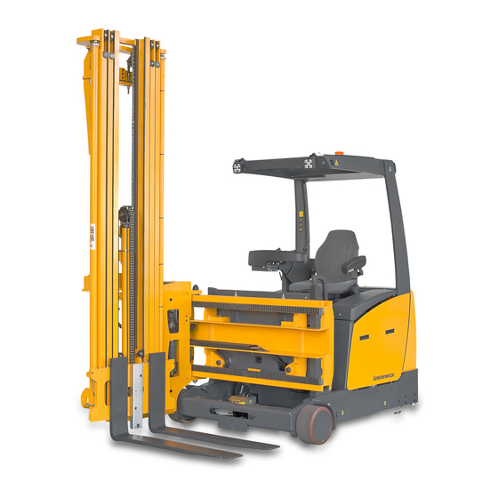
B Truck Description Application The EFX is an electric tri-lateral stacker. The EFX is designed to lift. lower and transport on level surfaces in accordance with the VDMA guideline. Open bottom pallets or pallets with diagonal boards can be lifted outside the range of the load wheels. - Page 18 Safety clearance (design safety distance) The racking systems must be set up for the EFX. The safety clearance in the narrow aisle required by the manufacturer between the following truck components and the racking system must be observed: – The safety clearance on both sides between the swivel traverse frame and the racking and between the racking and the stored goods.
-
Page 19: Travel Direction Definition
Travel direction definition The following determinations have been made for travel direction specification: Item Travel direction Left Drive direction Load direction Right... -
Page 20: Assemblies And Functional Description
Assemblies and Functional Description Functional Description Safety mechanisms – An enclosed truck geometry with rounded edges ensures safe truck handling. The overhead guard protects the operator from falling objects. – The drive wheel and the load wheels are protected by a solid skirt. A slight danger nevertheless remains for third parties. - Page 21 Emergency Stop safety feature – If an error is detected by the controller the truck automatically brakes to a halt. Control indicators on the driver’s display indicate the emergency stop. Each time the truck is switched on, the system performs a self test which only releases the parking brake (emergency stop) if the functional test is positive.
- Page 22 Steering – Extremely smooth steering with threephase drive system (sturdy and maintenance-free threephase motor with no wear parts). – The steering wheel is integrated in the control panel. The position of the steered drive wheel is shown in the driver's display. The maximum steer angle is ± 90°. –...
- Page 23 Hydraulic system – All hydraulic operations are controlled by a sturdy, maintenance-free AC motor with no wear parts and with a flanged low emission gear pump. – Oil is distributed via magnetic switch valves. The varying oil requirements are controlled by the speed of the motor. –...
- Page 24 – Radio with CD player and MP3 interface. – Mechanical and electrical interfaces for material flow management systems. – Jungheinrich ISM: Information system for truck management (o). – Modular system of lift and travel cut-outs plus speed reductions. – Jungheinrich Warehouse Navigation: –...
- Page 25 Rack Height Select (o) – Rack Height Select can be used both to lift and lower the load as well as for stacking and retrieving. – With Rack Height Select, the operator can select the required lift height via a keypad.
-
Page 26: Assembly Overview
Assembly Overview 26,27 Item Description t Steering wheel t Control panel and driver's display t "Hydraulic functions" control lever t Key switch t Emergency disconnect switch t Operator position t Overhead guard o Strobe light or warning beacon o Laser-beam rack-compartment display o Working lights t Lift mast o Rear-view mirror (left- and right-hand) - Page 27 Item Description t Accelerator pedal o ISM access module (on the right next to the handle (17)) t Storage compartment t Swivel traverse frame o Front sensor for wire-guidance system (not shown) o Front scanner for personal protection system (not shown) t Fork (load handler) t Battery cover t Load wheel...
-
Page 28: Technical Specifications
Technical Specifications The technical specification is given according to the German guideline "Type sheets for industrial trucks". Technical modifications and additions reserved. Values indicated with *) may vary depending on the configuration of the truck (e.g. mast, etc.). -
Page 30: Performance Data
Performance data Description EFX 410 EFX 413 Q Capacity (where D = 600 mm) 1000 1250 D Load centre distance Operation Tri-lateral stacker Travel speed without load (unguided) km/h Travel speed with load (unguided) km/h Travel speed without load (RG) -
Page 31: Dimensions (As Per Data Plate)
Dimensions (as per data plate) - Page 32 EFX 410 with 400 telescopic mast (ZT mast) EFX 413 with 400 telescopic mast (ZT mast) with a strobe light this dimension increases to approx. 2377 mm with transponder readers (RFID readers) this dimension is reduced to approx. 45...
- Page 34 EFX 410 with 400 telescopic mast (ZT mast) EFX 413 with 400 telescopic mast (ZT mast) with a strobe light this dimension increases to approx. 2377 mm with transponder readers (RFID readers) this dimension is reduced to approx. 45...
-
Page 35: Mast Versions
(e. g. when driving through doorways, when the ceiling is low, etc.). uWhen operating the truck, ensure that the lift mast does not collide with obstacles. Description EFX 410 EFX 413 Mast height lowered 2305 – 3875 2305 – 3875 Free lift Lift 3000 –... - Page 36 (e. g. when driving through doorways, when the ceiling is low, etc.). uWhen operating the truck, ensure that the load does not collide with obstacles. Description EFX 410 EFX 413 Mast height lowered 2100 – 3180 2100 – 3180 Free lift 1410 –...
-
Page 37: Weights
0 mm 0 kg 3145 kg EFX 410 90 mm 152 kg 3297 kg 180 mm 304 kg 3449 kg 0 mm 0 kg 3445 kg EFX 413 90 mm 152 kg 3597 kg 180 mm 304 kg 3749 kg... - Page 38 Example: Required information: (see truck data plate) – Type of industrial truck = EFX 413 – Net weight of the industrial truck without battery = 4350 kg Formula: B = A - 3445 kg = 4350 kg - 3445 kg = 905 kg...
- Page 39 EFX 410 with 400 telescopic mast (ZT mast) EFX 413 with 400 telescopic mast (ZT mast) with a strobe light this dimension increases to approx. 2377 mm with transponder readers (RFID readers) this dimension is reduced to approx. 45...
-
Page 40: Wheels, Chassis
295 mm x 144 mm Wheels, rear (drive wheel) 343 mm x 110 mm Wheels, number of, front (load wheel) Wheels, number of, rear (drive wheel) *= driven EFX 413 Description EFX 413 Tyres Vulkollan Wheels, front (load wheel) 295 mm x 144 mm... -
Page 41: Engine Data
EN norms Noise emission level – EFX 410: 66,5 dB(A) – EFX 413: 66,5 dB(A) in accordance with EN 12053 as harmonised with ISO 4871. The noise emission level is calculated in accordance with standard procedures and takes into account the noise level when travelling, lifting and when idle. The noise... - Page 42 Vibration Weighted vibration acceleration on seat: – EFX 410: aw,zS = 0,48 m/s² – EFX 413: aw,zS = 0,48 m/s² in accordance with EN 13059. The internal accuracy of the measuring chain for at 21°C at ± 0,02 m/s². Further deviations may occur in particular through the positioning of the sensor and different driver weights.
-
Page 43: Conditions Of Use
Conditions of use WARNING! Operation under extreme conditions Operating the industrial truck under extreme conditions can lead to malfunctions and accidents. uSpecial equipment and authorisation are required if the truck is to be constantly used in extreme conditions, especially in dusty or corrosive atmospheres. uIt is forbidden to operate the truck in areas where there is a risk of explosion. -
Page 44: Electrical Requirements
Electrical requirements The manufacturer certifies compliance with the requirements for the design and manufacture of electrical equipment, according to EN 1175 "Industrial Truck Safety - Electrical Requirements", provided the truck is used according to its purpose. -
Page 45: Identification Points And Data Plates
Identification points and data plates Warnings and notices such as capacity charts, strap points and data plates must be legible at all times. Replace if necessary. Indication Points... - Page 46 Item Description Attachment points for crane lifting Capacity decal Warning label, “Laser radiation” Warning label, "Do not step onto or beneath the load; risk of crushing" Warning label, “Read operating instructions” Warning label, "Wear seat belt" (o) Attachments or special attachments (o) capacity plate, see page 47 Test plaque (o) Information label, "Travel and brake pedals"...
-
Page 47: Data Plate
Data plate The illustration shows the standard version for EU member states. The data plate may differ in other countries. Item Description Item Description Type Year of manufacture Serial number Load centre (mm) Rated capacity (kg) Output Battery voltage (V) Min./max. -
Page 48: Truck Capacity Plate
Truck capacity plate WARNING! Replacing the forks can cause accidents If you replace the forks with ones that differ from the originals, the capacity will change. uWhen adding forks that differ from the ones originally supplied, an additional capacity plate must be attached to the truck. Example: Fitting longer forks to the truck uAdding forks that differ from the ones originally supplied requires the manufacturer s approval. -
Page 49: Attachment Capacity Plate
Attachment capacity plate The attachment capacity plate indicates the industrial truck's capacity Q (kg) in conjunction with the attachment fitted. The serial number on the capacity plate must match the data plate of the attachment, as the specific capacity for each truck is specified by the manufacturer. -
Page 50: Stability
Stability WARNING! Loss of stability can cause accidents The stability as indicated in the capacity plate can only be guaranteed with the components (battery, mast) as shown on the data plate. uAlways use batteries approved by the manufacturer, see page 73. The truck's stability has been tested according to latest technological standards. -
Page 51: C Transport And Commissioning
C Transport and Commissioning Transport The truck can be transported in two different ways, depending on the height of the mast and the local conditions. – Vertically with the mast and load handler assembled (for low heights) – Vertically with the mast and load handler disassembled (for large truck heights). - Page 52 Safety Instructions for Assembly and Commissioning WARNING! Incorrect assembly can result in accidents The assembly of the truck at the application site, commissioning and operator training must only be performed by the manufacturer's customer service representatives who have been specially trained for these tasks. uThe hydraulic and electrical lines may only be connected to the basic truck / mast interface when the mast has been properly assembled.
-
Page 53: Lifting By Crane
Lifting by crane WARNING! All persons involved in loading by crane must be trained Incorrect crane loading procedures due to untrained personnel can cause the truck to fall. There is a risk of injury to personnel and a risk of material damage to the truck. -
Page 54: Lifting By Crane With Mast Assembled
Lifting by crane with mast assembled Item Component Support to protect the crane slings from sharp edges WARNING! Crane slings can tear, resulting in accidents Crane slings can tear when routed over sharp edges, causing the load to fall. uDo not route the crane lifting gear over sharp edges. If this is not possible, protect the crane lifting gear with suitable supports such as foam. - Page 55 Procedure For details of the weight of the "basic truck with mast assembled" to be taken into account when lifting by crane, refer to the truck data plate, see page 45. WARNING! Using unsuitable attachment points can cause to load to fall. When loading by crane, using the attachment point on the lift mast can cause the basic truck to fall.
-
Page 56: Lifting The Basic Truck By Crane
Lifting the basic truck by crane Item Component Support to protect the crane slings from sharp edges WARNING! Crane slings can tear, resulting in accidents Crane slings can tear when routed over sharp edges, causing the load to fall. uDo not route the crane lifting gear over sharp edges. If this is not possible, protect the crane lifting gear with suitable supports such as foam. - Page 57 Procedure Weight of the basic truck to be taken into account, see page 35. • Attach the crane lifting gear (77) to the attachment points (78,79) so that the truck cannot slip. • Attach the crane lifting gear (77) to both attachment points (78) on the overhead guard (11).
-
Page 58: Lifting The Mast By Crane
Lifting the mast by crane Item Component Support to protect the fastening belt from sharp edges WARNING! Torn fastening belts can cause accidents Fastening belts can tear when routed over sharp edges. uDo not route the fastening belts over sharp edges. If this is not possible, protect the fastening belts with suitable supports such as foam. - Page 59 • Raise the lift mast (15) and load it. • Set down the lift mast (15) safely: • Place the mast (15) carefully on two identical pallets (83). • Secure the lift mast (15) with the lashing straps (82) tightly on the pallets (83). •...
-
Page 60: Lifting The Battery By Crane
Lifting the battery by crane WARNING! All persons involved in loading by crane must be trained Incorrect crane loading procedures due to untrained personnel can result in the battery falling. There is a risk of injury to personnel and a risk of material damage to the battery. - Page 61 Safe lifting of the battery by crane Requirements – Remove battery from truck's battery compartment, see page 82. Tools and Material Required – Crane lifting gear, for capacity details refer to the battery data plate. – Pallet – Lashing strap Procedure The weight of the battery to be taken into account when loading by crane can be taken from the battery...
-
Page 62: Securing The Truck During Transport
Securing the truck during transport WARNING! Accidental movement during transport Improper fastening of the truck and mast during transport can result in serious accidents. uLoading must only be performed by specialist personnel trained for this purpose. The specialist personnel must be instructed in securing loads on road vehicles and handling load securing devices. - Page 63 Securing the mast for transportation Requirements – Secure the fork carriage (19) with a lashing strap (81) to prevent accidental movement. – Remove the mast. The mast can only be removed by the manufacturer's specialist customer service personnel who have been trained to do this. In exceptional cases this task may be performed by a customer service organisation authorised by the manufacturer.
-
Page 64: Basic Truck Transport Retainer
Basic truck transport retainer Item Component Support to protect the fastening belt from sharp edges WARNING! Torn fastening belts can cause accidents Fastening belts can tear when routed over sharp edges. uDo not route the fastening belts over sharp edges. If this is not possible, protect the fastening belts with suitable supports such as foam. - Page 65 – Two hard wooden blocks with identical dimensions and composition. – Two identical wedges. Procedure • Secure the support frame (18) with lashing straps to prevent accidental movement. • Relieve the drive wheel (38). To do this, place the hard wooden blocks (94) under the chassis on either side at the height of the drive wheel (38).
-
Page 66: Transport Retainer For Basic Truck With The Mast Assembled
Transport retainer for basic truck with the mast assembled Item Component Support to protect the fastening belt from sharp edges WARNING! Torn fastening belts can cause accidents Fastening belts can tear when routed over sharp edges. uDo not route the fastening belts over sharp edges. If this is not possible, protect the fastening belts with suitable supports such as foam. - Page 67 – Two identical wedges. – Wooden plank, pallet or rubber mat. Procedure • Secure the support frame (18) with lashing straps to prevent accidental movement. • From the fork carriage (19) to the front of the transport vehicle, form a positive fit using wooden beams, a pallet or a rubber mat (95).
-
Page 68: Using The Truck For The First Time
Using the Truck for the First Time Safety Instructions for Assembly and Commissioning WARNING! Incorrect assembly can result in accidents The assembly of the truck at the application site, commissioning and operator training must only be performed by the manufacturer's customer service representatives who have been specially trained for these tasks. - Page 69 WARNING! Trapping hazard in the swivel and traverse area of the attachment There is a trapping hazard in the attachment area while the attachment is traversing and swivelling. uKeep all personnel out of the hazardous area during hydraulic operations. uInstruct other people to move out of the hazardous area of the industrial truck. uStop working with the truck if people do not leave the hazardous area.
-
Page 70: Commissioning
Commissioning Preparing the truck for operation after delivery or transport Requirements – Unload the truck from the transport vehicle, lorry or trailer. – Install the mast. The mast can only be assembled by the manufacturer's specialist customer service personnel who have been trained to do this. In exceptional cases this task may be performed by a customer service organisation authorised by the manufacturer. -
Page 71: Tilt Safety Device
Tilt safety device Depending on the tilt test the EFX may be supplied with tilt safety devices (36). The tilt safety devices are fitted to the left and right of the rear truck chassis. When a tilt safety device (36) is used, under the right side panel (42) an "X" is engraved in the chassis (41) after the serial number (see page 43). -
Page 73: D Battery - Servicing, Recharging, Replacement
D Battery - Servicing, Recharging, Replacement Safety Regulations Governing the Handling of Lead-Acid Batteries Maintenance personnel Batteries may only be charged, serviced or replaced by trained personnel. This operator manual and the manufacturer’s instructions concerning batteries and charging stations must be observed when carrying out the work. Fire Protection Do not smoke and avoid naked flames when handling batteries. -
Page 74: General Notes On Handling Batteries
The use of unsuitable batteries that have not been approved by Jungheinrich for the truck can lead to a deterioration of the braking system during energy recovery operations and also cause considerable damage to the electrical control system. -
Page 75: Battery Types
DIN 43531-A. The following table shows which combinations are included as standard: Truck type Battery type Voltage Capacity EFX 410 48 V 500 Ah 4 PzS 500 EFX 413 EFX 410 48 V 625 Ah 5 PzS 625 EFX 413 EFX 410 48 V 750 Ah 6 PzS 750... -
Page 76: Dimensions Of The Battery Compartment
Dimensions of the battery compartment WARNING! Loss of stability can cause accidents The weight and dimensions of the battery have a considerable effect on the operational safety of the industrial truck. When replacing the battery equipment, make certain that the battery dimensions, types and weights of the replacement battery are identical with those of the previously used battery. - Page 77 Truck type Length (L) Width (W) Height (H) 1060 mm 640 mm 640 mm EFX 410 Maximum battery height = 627 mm 1060 mm 640 mm 640 mm EFX 413 Maximum battery height = 627 mm...
-
Page 78: Exposing The Battery
Exposing the battery WARNING! An unsecured truck can cause accidents Parking the truck on an incline or with a raised load handler is dangerous and is strictly prohibited. uPark the truck on a level surface. In special cases the truck may need to be secured with wedges. - Page 79 • Unlatch the battery cover (29). Push the "battery cover locking" lever (98) through the opening (97) in arrow directions "A“ . • Tilt back the battery cover (29) to the stop (see arrow direction "B“). The battery cover (29) is open and prevented from closing automatically. WARNING! Collision hazard when operating the truck Collisions with personnel and equipment can result if the truck is operated with open...
-
Page 80: Charging The Battery
Charging the battery WARNING! The gases produced during charging can cause explosions The battery produces a mixture of nitrogen and hydrogen (electrolytic gas) during charging. Gassing is a chemical process. This gas mixture is highly explosive and must not be ignited. uSwitch the charging station and truck off first before connecting/disconnecting the charging cable of the battery charging station to/from the battery connector. - Page 81 Procedure • Disconnect the battery (33). • Connect the battery connector (33) to the charging cable of the stationary charger. NOTICE Risk of fire and material damage The charger must be adapted to the battery in terms of voltage and charge capacity. Always follow the safety regulations of the battery and charger station manufacturers.
- Page 82 WARNING! The gases produced during charging can cause explosions The battery produces a mixture of nitrogen and hydrogen (electrolytic gas) during charging. Gassing is a chemical process. This gas mixture is highly explosive and must not be ignited. uSwitch the charging station and truck off first before connecting/disconnecting the charging cable of the battery charging station to/from the battery connector.
- Page 83 After a fully discharged battery has been completely re-charged and the truck switched on, it may take a few seconds before the truck is operational. During this time the battery symbol in the driver's display flashes.
-
Page 84: Battery Removal And Installation
Battery removal and installation WARNING! Accident risk during battery removal and installation Due to the battery weight and acid there is a risk of trapping or scalding when the battery is removed and installed. uNote the "Safety regulations for handling acid batteries" section in this chapter. uWear personal protective equipment (e.g. - Page 85 Procedure • Disconnect the battery connector (33). • Disassemble the side panels (42): • Pull up and lift out the side panels (42) (see arrow direction "A"). • Unlatch and remove the battery retainer (102): • Turn the handle (101) approx. 180° anticlockwise (see arrow direction "B"). •...
- Page 86 CAUTION! Hand / arm trapping hazard There is a risk of trapping when you close the battery cover and fit the side panels, battery retainers, battery locks and battery. uMake sure there is nothing between the parts mentioned above and the truck when you fit the battery, retainers and side panels.
- Page 87 • Push the battery (99) off the roller stand as far as the stop in the truck's battery compartment (see arrow direction "E"). • Insert and lock the battery retainer (102): • Insert the battery retainer (102) in the chassis (see arrow direction "C"). •...
-
Page 88: "Battery Lock" Sensors (O)
"Battery lock" sensors (o) CAUTION! An unsecured battery can result in accidents If the battery retrainers are not applied in the chassis, the battery may slide out of the battery compartment when the truck moves. uApply the battery lock in the chassis. uOnly short shunting operations can be performed without the battery locks. - Page 89 The speed restriction is removed once the battery retainer(s) is/are inserted in the chassis. The "battery lock not applied" symbol (103) fades out. The truck can now travel again at the approved speed. Hydraulic operations are not affected if the battery retainers are not in place.
-
Page 91: Operation
E Operation Safety Regulations for the Operation of the Forklift Truck Driver authorisation The truck may only be used by suitably trained personnel, who have demonstrated to the proprietor or his representative that they can drive and handle loads and have been authorised to operate the truck by the proprietor or his representative. - Page 92 Hazardous area WARNING! Risk of accidents/injury in the hazardous area of the truck A hazardous area is defined as the area in which people are at risk due to travel or lifting operations of the truck, its load handler or the load. This also includes the area within reach of falling loads or lowering/falling operating equipment.
- Page 93 Safety devices, warning signs and warning instructions Safety devices, warning signs (see page 43) and warning instructions in the present operating instructions must be strictly observed. Warnings and notices such as capacity charts, strap points and data plates must be legible at all times.
-
Page 94: Displays And Controls
Displays and Controls Controls and displays on the control panel... - Page 95 Item Control / display Function t Steers the truck in the required direction. Steering wheel Switches control current on and off. Key switch and key Removing the key prevents the truck from being switched on by unauthorised personnel. Emergency Disconnects the main power supply, all truck Disconnect switch operations are disabled.
- Page 96 Item Control / display Function t Provides infinitely variable braking control. Brake pedal t Infinite travel speed control. Accelerator pedal In addition to the key switch. Releases the truck response with card or transponder. ISM access module o – Time out monitoring –...
- Page 97 Item Control / display Function Changes menu: When you press the "Quit sub- “Quit sub-menu” menu" button the menu currently shown in the button driver's display changes to the higher-level menu. Cursor keys for Controls and settings for standard functions (e.g. special hydraulic setting the time) and additional functions (e.g.
- Page 98 Item Control / Display Function Controls the hydraulic functions, e. g.: – Lifting and lowering the load handler "hydraulic functions" – Rotating the fork carriage in conjunction with the control lever "fork carriage rotate" button (119) – Traversing the fork carriage in conjunction with the "fork carriage traverse"...
-
Page 99: Driver's Display
Driver's display Item Symbol Display Function Truck is ready for operation. "Parking brake Indicates the truck is stationary applied" warning Parking brake (drive wheel brake) is lamp applied. Displays the number of service hours "Service hours" since the truck was started for the first time. - Page 100 Item Symbol Display Function Indicates the current steer angle with Steer angle display reference to the centre position. Rail guidance: Steer angle display is replaced by the following symbols: Symbol lights up as soon as the truck is "Truck guided (with automatically guided and has received an aisle detection)"...
- Page 101 Item Symbol Display Function Wire guidance: Steer angle display is replaced by the following symbols: “Acquisition in Symbol lights up as soon as the truck has progress” acquired the guide wire. Symbol lights up as soon as the truck is "Truck guided (with automatically guided on the wire and has aisle detection)"...
- Page 102 Item Symbol Display Function Display: – Truck model 125 "Truck features" – Truck features (wire guidance / rail guidance) – Serial number Shows the lift height of the load handler “Overall lift” after referencing. "Main-lift raising" t Requests raising of the main lift. referencing "Main-lift lowering"...
- Page 103 Item Symbol Display Function Indicates that there are persons/ obstacles in the warning field of the “Warning field personal protection system in the narrow infringement” aisle, see page 244. indicator The truck brakes. During this time the travel speed is restricted to creep speed (2,5 km/h).
- Page 104 Item Symbol Display Function “Guide wire Wire guidance sensors that have detection” detected the guide wire light up. "Dead man's switch Truck is ready for operation. not depressed" Dead man's switch not depressed. "Emergency Truck is ready for operation. disconnect switch Emergency disconnect switch pressed.
-
Page 105: Hourmeter
Item Symbol Display Function "Rack Height Select" / "horizontal positioning" symbols (o), see page 265 or see page 281. Denotes standard equipment Denotes optional equipment WG Wire guidance RG Rail guidance Hourmeter Prepare the truck for operation, see page 138 or see page 139. Service hours are counted while the truck is operational and the deadman button is pressed. -
Page 106: Bar Display" Battery Discharge Indicator
"Bar display" battery discharge indicator The standard setting for the battery discharge indicator / discharge monitor is based on standard batteries. When using maintenance-free or special batteries, the display and cut-out points of the battery discharge monitor must be set by manufacturer's service department. - Page 107 2.4.1 Battery discharge monitor with bar display When a battery is discharged to the permissible level (residual capacity), the battery symbol in the driver's display is empty and flashing. An indicator appears in the driver's display. The load handler can no longer be lifted. Battery symbol Meaning Battery is charged.
-
Page 108: Percentage Display" Battery Discharge Indicator (O)
"Percentage display" battery discharge indicator (o) The standard setting for the battery discharge indicator / discharge monitor is based on standard batteries. When using maintenance-free or special batteries, the display and cut-out points of the battery discharge monitor must be set by manufacturer's service department. - Page 109 2.5.1 Percentage display battery discharge monitor (o) If a battery is discharged to less than 31 % for wet-cell batteries or 41 % for gel batteries (residual capacity), the battery symbols flashes in the driver's display. The load handler can no longer be lifted below 21 % for wet-cell batteries and 31 % for gel batteries.
-
Page 110: Driver's Display Function Symbols
Driver's display function symbols Procedure The "Functions" key (104) underneath the symbols (137) in the driver's display activate confirm respective function. The symbol (137) has a dark background. following section describes the symbols for the displayed functions. Symbol and meaning Function Standard attachment, fork operation Changes the menu shown in the driver's... - Page 111 Symbol and meaning Function Indicates that it is possible to "Automatic synchronised synchronously rotate the fork carriage to fork rotation to the left " the left and traverse the attachment to symbol the right manually . Activates automatic synchronised "Automatic synchronised rotation of the fork carriage to the left and fork rotation to the left "...
- Page 112 Symbol and meaning Function Attachment, fork positioning / sideshift “Fork positioning / Changes the menu shown in the driver's sideshift menu change” display to the "fork positioner / sideshifter menu change" function. Changes menu: Pressing the "fork “Fork positioning / positioning / sideshift menu change"...
- Page 113 Symbol and meaning Function Personal Safety System (PSS) – Indicates that there are persons/ obstacles in the protection field of the personal protection system in the "Protection field narrow aisle, see page 245. infringement" symbol – Indicates missing activation frequency for the stationary personal safety system.
- Page 114 Symbol and meaning Function Attachment, fork operation, special attachment "2nd stacking depth" Indicates that the "2nd stacking depth" symbol function is possible. Activates the 2nd stacking depth of the telescopic forks. 2nd stacking depth" This hydraulic function is controlled with button the "hydraulic functions"...
- Page 115 Symbol and meaning Function Warnings Appears as soon as lift cut-out is “Fwd./rev. travel only due activated due to low battery capacity. to low battery capacity” The truck can now only move forward or symbol in reverse. Confirms lift cut-out for low battery “Acknowledge lift cut-out capacity and releases travel.
- Page 116 Symbol and meaning Function Indicates that the sub-menu (e. g. set “Quit sub-menu” symbol date/time, operator specific settings, etc.) can be left. Changes menu: After pressing the "quit sub-menu" key the menu currently “Quit sub-menu” button shown in the driver's display changes to the "truck functions"...
- Page 117 Symbol and meaning Function Guidance systems Indicates that wire guidance is available "Select frequency 1" with frequency 1 (similar to other symbol frequencies, maximum 5 frequencies). Activates wire guidance via frequency 1 "Select frequency 1" (sub-menu is quit automatically when button pressed for 1 sec.).
- Page 118 Symbol and meaning Function "Camera" symbol Indicates that the picture from the camera can be shown on the monitor. "Camera" key o Switches the camera on and off. "Weighing-system- Indicates that the weight measurement display zero setting" display can be set (tared) to ZERO, see symbol page 296.
-
Page 119: Preparing The Truck For Operation
Preparing the Truck for Operation WARNING! Risk of accidents in the hazardous area of the truck Before the truck can be started, operated or a load lifted, transported or lowered, the operator must ensure that there is nobody within the hazardous area. uInstruct other people to move out of the hazardous area of the truck. - Page 120 3.1.1 Visual external inspection of the whole truck for damage Procedure • Check truck for damage. • Check the overhead guard for damage. • Check operator position for damage. • Check the operator mat and steps are non-slip and damage-free. •...
- Page 121 3.1.2 Hydraulic system visual inspection Procedure • Check entire truck externally for signs of leakage: • check the hydraulic cylinders. • check the hydraulic ports. • check the lines. • check the hoses. WARNING! Damaged / leaky hydraulic cylinders, ports, lines and hoses must be replaced before the truck is started.
- Page 122 3.1.3 Battery visual inspection Procedure • Check the battery and battery container for damage. • Check the battery connector cable connections for damage. • Check battery cables and cell connectors for damage. • Check battery connectors for damage. • Check the battery connectors are secure. •...
-
Page 123: Entry And Exit
Entry and exit Requirements – Load handler fully lowered. Procedure Enter or leave the truck only from the left-hand side facing the truck. To enter and exit, hold onto the handle (139) and use the steps (140). • Enter or leave the truck. CAUTION! No more than one person may operate the truck at a time. -
Page 124: Setting Up The Operator Position
Setting up the operator position CAUTION! An unsecured driver's seat and control panel can result in falls and injury An unsecured driver's seat or control panel can slide during operation and result in accidents. uThe driver's seat and control panel must be locked in place when the truck is in operation. - Page 125 3.3.1 Adjusting the driver’s seat The procedure for adjusting the driver’s seat applies to standard models. For other models, follow the manufacturer’s setting instructions. When adjusting, ensure that all controls are within easy reach. WARNING! Risk of accidents and damage to health An incorrectly adjusted driver’s seat can result in accidents and damage to health.
- Page 126 Adjusting the backrest Procedure • Sit on the driver’s seat. • Pull the lever (142) to adjust the backrest. • Adjust the backrest tilt. • Release the lever (142) again. The backrest is locked. The backrest is now set. Adjusting the seat position CAUTION! An unsecured driver's seat can cause injury An unsecured driver's seat can slide out of its guide during travel, resulting in...
- Page 127 3.3.2 Control panel height adjustment The height of the control panel (118) can be vertically adjusted by 90 mm. CAUTION! An unsecured control panel can cause accidents and injury An unsecured control panel can slide during operation and result in accidents. uThe control panel must be locked in place when the truck is in operation.
- Page 128 3.3.3 Control panel longitudinal adjustment The control panel (118) can be adjusted horizontally by 200 mm. CAUTION! An unsecured control panel can cause accidents and injury An unsecured control panel can slide during operation and result in accidents. uThe control panel must be locked in place when the truck is in operation. uDo not adjust the control panel during operation.
-
Page 129: Checking, Putting On And Taking Off The Seat Belt
Checking, putting on and taking off the seat belt WARNING! Travelling without a seat belt increases the risk of injury. Accidents or personal injury can result if the seat belt is not worn or is modified. uAlways put the seat belt on before starting the industrial truck. uDo not modify the seat belt. - Page 130 Checking the seat belt Procedure • Check the attachment points for wear and damage. • Check the cover for damage. • Pull the belt out fully from the retractor and check for damage (loose seams, fraying and nicks). • Test the belt buckle and make sure the belt returns correctly into the retractor. Check the automatic locking system Procedure •...
- Page 131 Wear seat belt Procedure CAUTION! Excessive belt length can be hazardous If you sit on the front edge of the seat there is less protection afforded if the seat belt is too long. uPlace the seat belt as tightly as possible against your body. Sit on the driver's seat so that your back is resting against the backrest.
- Page 132 The correct procedure if the industrial truck tips over WARNING! What to do if the industrial truck tips over If the truck is in danger of tipping over, the operator should not jump out of the truck, and must keep his whole body inside the operator position.
-
Page 133: Industrial Truck Operation
Industrial Truck Operation Safety regulations for truck operation Travel routes and work areas Only use lanes and routes specifically designated for truck traffic. Unauthorised third parties must stay away from work areas. Loads must only be stored in places specially designated for this purpose. The truck must only be operated in work areas with sufficient lighting to avoid danger to personnel and materials. - Page 134 Travel surface The travel surface on which the truck is to be used on must be suitably maintained in order to provide the required traction for travel, steering and braking under the prevailing ambient conditions. The details on the truck data plate assume a level and dry travel surface. Other ground surfaces may have a negative affect on the stability of the truck.
- Page 135 Ground and ground conditions The ground on which the trucks are used must be level and smooth. There must not be any gaps, drainage systems etc. in this area. The ground must be well maintained to keep it free of contamination, obstacles and liquids that could affect the safe operation of the truck.
- Page 136 Travel conduct The operator must adapt the travel speed to local conditions. The operator must travel slowly for example when negotiating bends or narrow passageways, when passing through swing doors, at blind spots and when entering and leaving the narrow aisle. The operator must always observe an adequate braking distance between the forklift truck and the vehicle in front and must be in control of the truck at all times.
- Page 137 Visibility when travelling outside the narrow aisle The operator must look in the direction of travel and must always have a clear view of the route ahead. Loads which affect visibility must be positioned at the rear of the truck (travel in the drive direction, see page 153).
- Page 138 Negotiating lifts Lifts may only be negotiated if they have sufficient capacity, are suitable for driving on and authorised for truck traffic by the owner. The operator must satisfy himself of the above before entering lifts. The truck must enter lifts with the load in front and must take up a position which does not allow it to come into contact with the walls of the lift shaft.
- Page 139 Type of loads to be carried The operator must make sure that the load is in a satisfactory condition. Loads must always be positioned safely and carefully. Use suitable precautions to prevent parts of the load from tipping or falling down. Prevent liquid loads from sloshing out. WARNING! Accident risk when transporting liquid loads The following risks may be present when transporting liquid loads:...
-
Page 140: Preparing The Truck For Operation
Preparing the truck for operation Switching on the truck Requirements – Visual inspections and operations to be performed before starting daily operation, see page 117. – Connect the battery to the truck. – Insert and lock the battery latch. – Insert and lock the side panels correctly. –... -
Page 141: Preparing The Truck For Operation With An Additional Access Code (O)
Preparing the truck for operation with an additional access code Optionally, the truck can be prepared for operation with an additional 5 digit access code (from 00001 to 99999). Up to 99 different access codes can be set. The access codes can be set by the manufacturer's customer service department. - Page 142 Switching on the truck Requirements – Visual inspections and operations to be performed before starting daily operation, see page 117. – Connect the battery to the truck. – Insert and lock the battery latch. – Insert and lock the side panels correctly. –...
- Page 143 Procedure • In the driver's display (107) you will be prompted to enter your 5 digit access code. Enter the access code, to do this: Unless the correct access code is entered, none of the truck's functions will work. • Press the "Select" button (151) in the cursor field.
- Page 144 4.3.1 Log off user Log off user if the truck is abandoned Requirements – Truck operational, see page 139. Procedure • Press the "Quit sub-menu" key (108). The "Log off user" symbol (155) appears in the driver's display. Truck operations are inhibited in this menu.
-
Page 145: Date And Time Setting
Date and time setting Date and time format The date and time format can only be changed by the manufacturer's customer service department. Format Date Time Standard setting dd.mm.yyyy hh:mm:ss US setting mm.dd.yyyy hh:mm:ss am/pm Selecting the “Set Date/Time” menu Requirements –... - Page 146 Date and time setting Procedure • Press the "Select" button (151) in the cursor field. The first digit of the date is displayed "dark". • The operator cursor keys (156,157) to choose the required setting in the selected field: • Cursor key (156): increase number. •...
-
Page 147: Checks And Operations To Be Carried Out When The Truck Is Operational
Checks and operations to be carried out when the truck is operational DANGER! Truck defects can result in accidents Do not use the truck if the brake system, steering and/or hydraulic system is defective or faulty. If damage or other defects are discovered on the truck or attachment (special equipment), the truck must be taken out of service until it has been repaired. - Page 148 Procedure • Test warning indicators and safety devices: • Test the emergency disconnect function by pressing the emergency disconnect switch. The main circuit is disconnected and no truck operations can be performed. Now turn the emergency disconnect switch to unlock it. •...
-
Page 149: Main Lift Referencing
Main Lift referencing The symbols (159,160) indicate that a reference run is required, as indicated by the driver's display. After the reference run the controller releases all the truck operations at full speed. The reference run also adjusts the height display. Referencing the main lift Requirements –... - Page 150 Lift cut-out when referencing WARNING! An extended mast can cause accidents The lift cutout is an auxiliary function designed to support the operator which however does not release him from his responsibility to stop hydraulic operations e.g. when confronted with an obstacle. uWhen the lift cutout has been de-activated the truck must be operated with extra care in order to detect obstacles when the mast is extended.
- Page 151 Load handler post-referencing (sideshift / fork carriage) The load handler needs to be post-referenced in case the position of the load handler (attachment position, fork carriage rotation) has changed while the truck was switched off. When the truck is switched on again the "traverse reference run" (162) and "rotate reference run"...
- Page 152 "Rotate" referencing Procedure • Do not press the deadman button (20). • Press and hold down on the "Fork carriage rotate" button (119). • Carry out a fork carriage 180° rotation: • Turn the "Hydraulic functions" control lever (113) clockwise = Fork carriage right rotation.
-
Page 153: Emergency Disconnect
Emergency Disconnect CAUTION! Applying maximum braking can result in accidents Applying the Emergency Disconnect switch during travel will cause the truck to decelerate to a halt at maximum force. This may cause the load to slide off the load handler. There is a higher risk of accidents and injury. uDo not use the Emergency Disconnect switch as a service brake. - Page 154 Pressing the Emergency Disconnect switch Procedure • Press the Emergency Disconnect (9). All electrical functions are deactivated. The truck brakes to a halt at maximum brake force. Releasing the Emergency Disconnect switch Procedure • Turn the EMERGENCY DISCONNECT switch (9) to unlock it. •...
-
Page 155: Travel
Travel WARNING! Incorrect travel can cause accidents and injury Incorrect travel can cause accidents and therefore injury to the operator and / or third parties. uAlways transport a load outside the narrow aisle as low as possible, allowing for ground clearance. uDo not lean out of the truck while travelling. - Page 156 Industrial Truck Operation Requirements – Prepare the truck for operation, see page 138 or see page 139. – Carry out a mast reference run (main lift) to adjust the height display, see page 147. Procedure • Press and hold down the dead man's switch (20). •...
- Page 157 CAUTION! Danger when changing direction during travel Changing direction during travel can result in the truck travelling too quickly in the opposite direction if the operator does not take his foot of the accelerator pedal in time. Changing direction during travel causes the truck to decelerate sharply. uWhen the truck starts to move in the opposite direction, only depress the accelerator pedal lightly or not at all.
- Page 158 Changing direction during travel Requirements – Prepare the truck for operation, see page 138 or see page 139. Procedure • Drive the truck in the load or drive direction: • Press and hold down the dead man's switch (20). • Press the accelerator pedal (22). •...
-
Page 159: Steering
Steering Requirements – Prepare the truck for operation, see page 138 or see page 139. Procedure • Steering outside narrow aisles: • Turn the steering wheel (5) to the left or right, depending on the travel direction. The drive wheel position (124) is indicated on the driver's display (107). - Page 160 Braking with the brake pedal ( Procedure • Press down on the brake pedal (21) until you reach the required deceleration. The truck decelerates depending on the position of the brake pedal (21). Braking with the deadman button ( Procedure •...
-
Page 161: Negotiating Narrow Aisles
4.11 Negotiating narrow aisles 4.11.1 Negotiating narrow aisle with rail-guided trucks (o) WARNING! Unauthorised entry of narrow aisles by other trucks or people can cause accidents Unauthorised personnel must not enter narrow aisles (truck lanes in racking systems with safety distances < 500 mm), nor must any personnel cross through them. These work areas must be marked and identified accordingly. - Page 162 NOTICE Note the safety clearances between the truck and rack Refer to the following table for the safety clearances required by the manufacturer depending on the type of guidance system and the lift height (h Truck guidance in the narrow Lift height (h Safety clearance aisle...
- Page 163 Procedure Rail-guided trucks are fitted with sensors or RFID readers. These sensors activate aisle detection when the truck enters an aisle. WARNING! Faulty or loose guide rails can be dangerous Do not operate the truck in narrow aisles with faulty or loose guide rails. The lack of guidance could cause a collision between the truck and the racks.
- Page 164 Procedure • Determine the travel direction: • Push the travel direction switch (105) right = Travel in load direction • Push the travel direction switch (105) left = Travel in drive direction • Apply the accelerator pedal (22). The travel speed governed accelerator pedal (22).
- Page 165 Leaving the narrow aisle Procedure • Drive the truck completely out of the narrow aisle. • Bring the truck to rest. CAUTION! You can only change from automatic to manual steering once the truck has fully exited the narrow aisle. •...
- Page 166 4.11.2 Negotiating narrow aisles with wire-guided trucks (o) WARNING! Unauthorised entry of narrow aisles by other trucks or people can cause accidents Unauthorised personnel must not enter narrow aisles (truck lanes in racking systems with safety distances < 500 mm), nor must any personnel cross through them. These work areas must be marked and identified accordingly.
- Page 167 WARNING! Objects protruding out of the racks can be hazardous The operator of the truck in a narrow aisle can be injured by objects protruding from the racks (e. g. pallets, loads etc.). A collision between the truck and the protruding objects could also cause material damage to the truck and the rack construction.
- Page 168 Negotiating narrow aisles with wire-guided trucks Requirements – Narrow aisles must be equipped with a guide wire. – Prepare the truck for operation, see page 138 or see page 139.
- Page 169 Procedure Always attain the guide wire in the load direction if this is possible. This has the advantage that the time needed and the distance involved are less then when attaining the guide wire in the drive direction. • Press the dead man's switch. •...
- Page 170 Procedure • Determine the travel direction: • Push the travel direction switch (105) right = Travel in load direction • Push the travel direction switch (105) left = Travel in drive direction • Apply the accelerator pedal (22). The travel speed governed accelerator pedal (22).
- Page 171 Leaving the narrow aisle Procedure • Drive the truck completely out of the narrow aisle. • Bring the truck to rest. CAUTION! You can only change from automatic to manual steering once the truck has fully exited the narrow aisle. •...
-
Page 172: Diagonal Travel
4.12 Diagonal travel Requirements – Prepare the truck for operation, see page 138 or see page 139. – Drive the truck into the narrow aisle and establish automatic guidance, see page 159. Procedure • Press the dead man's switch (20). •... -
Page 173: Lifting / Lowering - Outside And Inside Narrow Aisles
4.13 Lifting / lowering – outside and inside narrow aisles 4.13.1 Load handler raise/lower WARNING! Accident risk when lifting and lowering Other people can be injured in the truck's hazardous area. The hazardous area is defined as the area in which people are at risk from the truck movement, the load handler, attachments etc. - Page 174 WARNING! Unauthorised lowering speeds can cause accidents The line break safety valve in the Main Lift hydraulic cylinders stops the load handler from lowering if the lowering speed is out of range (> 0,6 m/s). If the safety valve applies for an unauthorised lowering speed, determine the cause. uIf there no leakage in the hydraulic system, raise the Main Lift slightly and then lower it again slowly.
- Page 175 CAUTION! Positioning or blocking the load handler The lift chains may sag when positioning or blocking the load handler. There is a risk of the load handler dropping suddenly once no longer supported or when the block is released. If the load handler drops suddenly, the lift chains or hydraulic hoses may become damaged.
- Page 176 Requirements – Prepare the truck for operation, see page 138 or see page 139. Procedure • Press the dead man's switch (20). • To raise the load handler: • Turn the "hydraulic functions" control lever (113) clockwise. • To lower the load handler: •...
-
Page 177: Traversing / Rotating Outside And Inside Narrow Aisles
4.14 Traversing / rotating outside and inside narrow aisles WARNING! Risk of trapping when swivelling or moving the forks Other people can be injured in the truck's hazardous area. The hazardous area is defined as the area in which people are at risk from the truck movement, the load handler, attachments etc. - Page 178 WARNING! A faulty attachment can be hazardous Check the attachment daily for external signs of damage or defects. Faulty attachments can cause the load to fall. uReport any defects immediately to your supervisor. uTag out and decommission a faulty lift truck. uOnly return the truck to service when you have identified and rectified the fault.
- Page 179 4.14.1 Attachment traverse Requirements – Prepare the truck for operation, see page 138 or see page 139. Procedure • Do not press the deadman button (20). • Press and hold down on the "Attachment traverse" button (120). • Traverse attachment to the right: •...
- Page 180 4.14.2 Fork carriage rotation Requirements – Prepare the truck for operation, see page 138 or see page 139. Procedure • Do not press the deadman button (20). • Press and hold down on the "Fork carriage rotate" button (119). • Rotate fork carriage right: •...
- Page 181 4.14.3 Rotation cut-out The EFX is fitted with a rotation cut-out as standard. The rotation cut-out disables the "fork-carriage rotation" hydraulic function as soon as a load greater than 500 kg is lifted above 2 m. Symbols and function of the rotation cut-out when the attachment is in home position.
- Page 182 Symbols and function of the rotation cut-out when the attachment is not in home position. Requirements – Attachment is not in the home position: see page 192. – A load greater than 500 kg is on the load handler. – Load handler is raised above 2 m. Procedure •...
-
Page 183: Simultaneous Traversing/Rotation Outside And Inside Narrow Aisles
4.15 Simultaneous traversing/rotation outside and inside narrow aisles WARNING! Risk of trapping when swivelling or moving the forks Other people can be injured in the truck's hazardous area. The hazardous area is defined as the area in which people are at risk from the truck movement, the load handler, attachments etc. - Page 184 WARNING! A faulty attachment can be hazardous Check the attachment daily for external signs of damage or defects. Faulty attachments can cause the load to fall. uReport any defects immediately to your supervisor. uTag out and decommission a faulty lift truck. uOnly return the truck to service when you have identified and rectified the fault.
- Page 185 4.15.1 Manual traverse/rotate operation (t) In manual traverse/rotate operation the fork carriage rotates as the attachment is moving. Requirements – Prepare the truck for operation, see page 138 or see page 139. Procedure • Do not press the dead man's switch (20). •...
- Page 186 If the attachment is not in the home position, you can only travel, lift or lower at a reduced speed, see page 192.
- Page 187 4.15.2 Automatic traverse/rotate operation (o) In automatic traverse/rotate operation the fork carriage rotates as the attachment is moving. Requirements – Prepare the truck for operation, see page 138 or see page 139. Procedure • Do not press the dead man's switch (20). •...
- Page 188 If the attachment is not in the home position, you can only travel, lift or lower at a reduced speed, see page 192.
- Page 189 4.15.3 Manual synchronised rotation until forks are in centre position (o) The "synchronised rotation until forks are in centre position" function rotates the fork carriage through 90° from the home position and positions the attachment in the centre of the swivel traverse frame. Requirements –...
- Page 190 • Synchronised fork carriage rotation through 90° to the right and load handler traverse to the centre position: • Press and hold down the key (104) under the "synchronised rotation until forks are in centre position" symbol (176) until the fork carriage stops rotating. •...
- Page 191 4.15.4 Automatic synchronised rotation until forks are in centre position (o) The "synchronised rotation until forks are in centre position" function rotates the fork carriage through 90° from the home position and positions the attachment in the centre of the swivel traverse frame. Requirements –...
- Page 192 If the attachment is not in the home position, you can only travel, lift or lower at a reduced speed, see page 192.
-
Page 193: Parking The Truck Securely
4.16 Parking the truck securely WARNING! An unsecured truck can cause accidents Parking the truck on an incline, without the brakes applied or with a raised load or load handler is dangerous and is strictly prohibited. uPark the truck on a level surface. In special cases the truck may need to be secured with wedges. - Page 194 Park the truck securely, Procedure • Park the truck on a level surface. • Fully lower the load handler (28): • Press the dead man's switch (20). • Turn the "hydraulic functions" control lever (113) anticlockwise. • Traverse and rotate the attachment into the home position, see page 192. •...
-
Page 195: Order Picking And Stacking
Order picking and stacking Adjusting the forks WARNING! Unsecured and incorrectly positioned loads can cause accidents. Before lifting a load the operator must make sure that it has been correctly palletised and does not exceed the truck’s capacity. uInstruct other people to move out of the hazardous area of the truck. Stop working with the truck if people do not leave the hazardous area. - Page 196 WARNING! Incorrect fork adjustments can cause accidents To lift the load securely, the fork tines should be as far apart as possible and centrally positioned with respect to the fork carriage. The load centre of gravity must be centrally aligned between the forks. WARNING! Unsecured forks can cause accidents forks...
-
Page 197: Replacing The Forks
Replacing the forks WARNING! Faulty fork tines can cause accidents Faulty fork tines can cause the load to fall. uDo not operate the truck with faulty forks. uIf one fork tine is damaged, both fork tines must be replaced. uReport any defects immediately to your supervisor. uTag out faulty forks and withdraw them from use. - Page 198 CAUTION! Trapping risk when moving the forks You can trap your arms and legs when moving the forks on the fork carriage. uWear personal protective equipment (e.g. safety boots etc.) when replacing the forks. uAlways push the forks away from your body, never towards it. uSecure heavy forks with lifting slings and a crane before pushing them down from the fork carriage.
- Page 199 Disassembling the forks Requirements – Truck parked securely, see page 191. – Load handler lowered and forks not touching the ground. Procedure • Disassemble extension safety mechanism (178). • Lift up the locking lever (177). • Carefully push the fork tines (28) off the fork carriage (19).
- Page 200 Assembling the forks Requirements – Truck parked securely, see page 191. – Mast lowered. – Fork carriage raised so that the fork tine can be pushed onto the fork carriage. – Extension safety mechanism (178) disassembled. Procedure • Carefully push the fork tines (28) onto the fork carriage (19). •...
-
Page 201: Lifting, Transporting And Depositing Loads
Lifting, transporting and depositing loads WARNING! Unsecured and incorrectly positioned loads can cause accidents. Before lifting a load the operator must make sure that it has been correctly palletised and does not exceed the truck’s capacity. uInstruct other people to move out of the hazardous area of the truck. Stop working with the truck if people do not leave the hazardous area. - Page 202 5.3.1 Lifting a load from the side Requirements – Prepare the truck for operation, see page 138 or see page 139. – Load unit correctly palletised. – Fork spread for the pallet checked and adjusted if necessary, see page 193. –...
- Page 203 5.3.2 Raise the load from the front (standard attachment only) Requirements – Prepare the truck for operation, see page 138 or see page 139. – Load unit correctly palletised. – Fork spread for the pallet checked and adjusted if necessary, see page 193. –...
- Page 204 5.3.3 Transporting a load Requirements – Prepare the truck for operation, see page 138 or see page 139. – Load unit correctly lifted, see page 200 or see page 201. – Good ground conditions. Procedure Always transport loads with both forks. When transporting heavy loads always ensure that both forks are evenly laden.
- Page 205 5.3.4 Depositing a load from the side WARNING! Depositing loads can be hazardous A storage location that is unsuitable for the load can become damaged when depositing the load. Neighbouring rack components can also be damaged. uDeposit the load only in locations that are suitable for storage (in terms of dimensions and capacity).
- Page 206 Procedure • Press the dead man's switch. • Drive the truck carefully up to the storage location. • Raise/lower the load handler so that the load can enter the storage location without colliding. • Do not press the dead man's switch. •...
- Page 207 5.3.5 Depositing a load from the front WARNING! Depositing loads can be hazardous A storage location that is unsuitable for the load can become damaged when depositing the load. Neighbouring rack components can also be damaged. uDeposit the load only in locations that are suitable for storage (in terms of dimensions and capacity).
- Page 208 Procedure • Press the deadman button. • Drive carefully up to the storage location. • Set the attachment to the "front lifting" position: • Do not press the deadman switch. 90˚ • Traverse the attachment to the centre position, see page 177.
-
Page 209: Troubleshooting
Troubleshooting Troubleshooting This chapter enables the operator to localize and rectify basic faults or the results of incorrect operation himself. When trying to locate a fault, proceed in the order shown in the remedy table. If, after carrying out the following remedial action, the truck cannot be restored to operation or if a fault in the electronics system is displayed with a corresponding error code, contact the manufacturer’s service department. - Page 210 Fault Possible Cause Remedy Truck does – Battery connector – Check battery connector and connect not start not plugged in to the truck if necessary. – Emergency – Release the emergency disconnect disconnect switch switch. see page 151). pressed – Key switch turned off – Turn on key switch (see page 138). –...
- Page 211 Fault Possible Cause Remedy Rapid travel – Load handler raised – Lower the load handler below 0,5 m. disabled above 0,5 m. – Attachment is not in – Traverse the attachment to the home the home position position (see page 192). –...
- Page 212 Fault Possible Cause Remedy 4917 – A key/ function-pre- – Do not press the key/ function-pre- select key (wire select key(wire guidance on/off, guidance on/off, attachment traverse, fork carriage attachment traverse, rotation); switch the truck off and on fork carriage again.
-
Page 213: Emergency Stop Device
Emergency stop device When the automatic emergency stop device applies (e.g. if the wire is abandoned, electrical steering fails) the truck brakes to a halt. Determine the cause of the fault and eradicate it before starting up the truck again. When starting the truck again, follow the manufacturer's instructions as indicated in the present operating instructions (see page 131). - Page 214 WARNING! Lowering the load handler can result in injuries The hazardous area is defined as the area in which people are at risk from the mast, the load handler or the load. This also includes areas which can be reached by falling loads or lowering operating equipment.
- Page 215 Load handler emergency lowering Requirements – Load handler is not in the rack. Tools and Material Required – Allen key (key width 6) to undo the lowering valve (181). Procedure If necessary, the load handler can be lowered from below by the operator or an assistant.
- Page 216 The load handler is lowered. WARNING! Only return the truck to service when you have identified and rectified the fault.
-
Page 217: Travel Cutout Override (O)
Travel cutout override (o) WARNING! The truck can cause accidents The travel cut out is an auxiliary function to assist the operator. However, it does not release him from his responsibility to monitor the braking functions – for example braking at the aisle end or in front of an obstacle and the initiation of braking, etc. – and to initiate braking if necessary. - Page 218 Driving the truck despite travel cut-out Procedure • Press the dead man's switch (20). • Press and hold down the key (104) under "travel cut-out override" symbol (182). • Determine the travel direction: • Pushing travel direction switch (105) to the right = travel in load direction.
-
Page 219: Lift Cutout Override (O)
Lift cutout override (o) If local conditions require, an automatic lift cutout can be installed to be activated from a given lift height. The automatic lift cutout prevents the Main Lift from raising. The driver's display shows the "Lift cutout override" symbol (161). WARNING! An extended mast can cause accidents The lift cutout is an auxiliary function designed to support the operator which... - Page 220 Lift cutout override Procedure • Press the deadman button (20). • Press and hold down on the button (104) under "Lift cutout override" symbol (161). • Turn the "Hydraulic functions" control lever (113) clockwise. The Main Lift is raised. Lift cutout is deactivated.
-
Page 221: Lower Cutout Override (O)
Lower cutout override (o) If local conditions require, an automatic lower cutout can be installed to be activated from a given height. The automatic lower cutout prevents the Main Lift from being lowered. The driver's display shows the "Lower cutout override" symbol (183). WARNING! Placing the load handler can be hazardous The lower cutout is an auxiliary function designed to support the operator which... - Page 222 Lower cutout override Procedure • Press the deadman button (20). • Press and hold down on the button (104) under "Lower cutout override" symbol (183). • Turn the "Hydraulic functions" control lever (113) anti-clockwise. The Main Lift is lowered. The lower cutout is deactivated.
-
Page 223: End Of Aisle Safety Device (O)
End of aisle safety device (o) Trucks with the end of aisle safety device brake before the aisle exit or in the transfer aisle. There are two basic versions for this: 1. Braking to a halt 2. Braking to 2.5 km/h Other variants (affecting the subsequent travel speed, lift height etc.) are available. - Page 224 2. Braking up to 2.5 km/h When the truck passes over the aisle end safety devices (route measurement, magnets, ...) in the direction of the end of the aisle, it brakes to 2.5 km/h and can be driven out of the narrow aisle at this speed. WARNING! The stopping distance depends on the travel speed.
-
Page 225: Wg Emergency Operation (Event Messages 3670 / 3752)
WG emergency operation (event messages 3670 / 3752) If the wire-guided truck's antenna leaves the pre-determined range of the guide wire, an emergency stop is immediately triggered. The driver's display flashes the "wire guidance fault" symbol and displays the event messages "3670"... -
Page 226: Recovering The Truck From A Narrow Aisle / Moving The Truck Without A Battery
If you cannot start the truck again after an automatic or manual Emergency Stop, despite having rectified the problem, turn the truck off and on again with the key switch. Then perform a reference run (see page 147) and carry out the above items again. The truck is now operational again. - Page 227 6.9.1 Release and activate the drive wheel brake WARNING! Accidental truck movement When the brakes are de-activated the truck must be parked on a level surface, since the brakes are no longer effective. uDo not release the brake on slopes or inclines. uDo not park the truck with the brake released.
- Page 228 • Remove the set screws (184) from the bracket (185) above the drive wheel brake (187). • Insert the set screws (184) into the drive wheel brake (187) above the drive motor (186) and tighten them with the two hex. nuts. The two set screws (184) are used to tension (unlock) the compression springs which activate the parking brake, so that the truck does not brake when de- energised.
- Page 229 WARNING! An unsecured truck can cause accidents Parking the truck on an incline or with a raised load handler is dangerous and is strictly prohibited. uPark the truck on a level surface. In special cases the truck may need to be secured with wedges.
- Page 230 Activating the drive wheel brake Requirements – Drive wheel brake wheel. – Truck parked securely. Procedure • Prevent the truck from moving accidentally, e. g. by placing wedges under the wheels. • Disassemble the drive compartment cover (35), see page 334. •...
- Page 231 6.9.2 Steering the truck without its own drive system CAUTION! A non-steered truck can cause accidents It may not be possible to steer the truck if the steering system is damaged. The truck can only be steered without its own drive system when it is stationary. uDo not adjust the truck's steering angle during a recovery operation.
- Page 232 Adjusting the steer angle Requirements – Load handler fully lowered, see page 171 or see page 211. Tools and Material Required – Open-ended spanner (opening: 14) Procedure • Switch off the truck; to do this: • Turn the key in the key switch (8) to the left as far as the stop and remove the key.
- Page 233 6.9.3 Recovering the truck from a narrow aisle WARNING! Accident risk Other people can be injured if the truck is towed incorrectly. uOnly use vehicles to tow the truck which have sufficient tow and brake forces for the trailer load without its own braking system. uAlways tow the truck at walking pace.
- Page 234 WARNING! Risk of accidents and trapping during recovery operations During recovery operations there is a risk of accidents and trapping from the truck being recovered. uRecover the truck carefully and slowly. uDo not stand between the tow truck and the recovered truck during a recovery operation.
- Page 235 Recovering the truck in the load direction with and without load Requirements – Attachment in home position, see page 192. – Load handler fully lowered, see page 171 or see page 211. – Drive wheel brake released, see page 225. Tools and Material Required –...
- Page 236 WARNING! Risk of injury during recovery operations Do not stand between the tow truck and the recovered truck during a recovery operation. Recover the truck carefully and slowly in the load direction. If the steering angle has to be changed during a recovery operation, brake until the truck comes to a halt.
- Page 237 Recovering the truck in the drive direction with and without load Requirements – Attachment in home position, see page 192. – Load handler fully lowered, see page 171 or see page 211. – Drive wheel brake released, see page 225. Tools and Material Required –...
- Page 238 If the steering angle has to be changed during a recovery operation, brake until the truck comes to a halt. CAUTION! A non-steered truck can cause injury The truck can only be steered without its own drive system when it is stationary (see page 229).
-
Page 239: Personal Safety System (O)
Personal safety system (o) Personal Protection System (PPS) The truck's integrated personal protection system (PSS) is designed to protect persons. The Personal Protection System (PSS) is used with industrial trucks in warehouse systems where pedestrians are not permitted to be in narrow aisles at the same time as industrial trucks. -
Page 240: Functional Description
Functional description – Mobile personal protection system with laser scanner based obstacle detection. – Apron field protection. – Optimum integration in the truck. – Easy adjustment / settings to match warehouse environment. – Automatic speed reduction / stopping in front of obstacles / personnel / other industrial trucks. -
Page 241: Environmental Awareness
7.2.2 Special functions depending on the ground conditions – Aisle type identification within a warehouse. – Speed reductions for escape routes within the lane. – Stopping for escape routes within the lane. – Zone change within a lane with short range recognition. –... -
Page 242: Cleaning The Laser Scanner Front Screen
Cleaning the laser scanner front screen The material required to clean the front screen of the laser scanner is outlined in "Consumables", see page 329. Requirements – Laser scanner under the load axle: Load handler fully lowered, see page 171. Attachment in home position, see page 192. -
Page 243: Displays On The Seven Segment Display And Indicator Light (Led)
Displays on the seven segment display and indicator light (LED) The seven segment display and the indicator light (LED) on the laser scanner act as the display for the operator and the customer service engineer. Display LED signal Description – Protection field clear, no object in protection field –... - Page 244 Other seven segment and indicator light (LED) error displays are relevant only to the manufacturer’s customer service department. Troubleshooting must only be performed by the manufacturer’s customer service department. The manufacturer has a customer service department specially trained for these tasks. In order for customer services to respond quickly and specifically to the fault, the following information is essential: - Truck serial number...
-
Page 245: Daily Checks Before Starting The Personal Protection System
Daily checks before starting the Personal Protection System – Check the front screens of the Personal Protection System laser scanner for contamination and clean as required (see page 240). – Cycle test (see page 243) 7.6.1 Cycle test NOTICE To ensure the correct operation of the personal protection system a cycle test must be carried out after a 24 hour timer has expired or each time the truck is switched off and on again. -
Page 246: Personal Safety System
Personal safety system 7.7.1 No obstacles and / or persons detected Provided there are no persons and / or obstacles in the PPS warning or protection fields, the truck can travel at the maximum speed setting. 7.7.2 Obstacles and / or persons in the warning field Requirements –... - Page 247 7.7.3 Obstacles and / or persons in the protection field Protection field infringements are displayed "protection field infringement" symbol (193). protection field infringements the truck also brakes to a halt. The obstacle or person are no longer in the protection field Requirements –...
- Page 248 • Press the dead man's switch (20). • Press the accelerator pedal (22). Depending on the truck's settings, the truck can be operated without restriction over a certain distance or for a certain time in the set direction. The maximum travel speed is restricted to 2,5 km/h.
-
Page 249: Optional Equipment
Optional equipment Sideshifter / Fork positioner (o) WARNING! A faulty attachment can be hazardous Check the attachment daily for external signs of damage or defects. Faulty attachments can cause the load to fall. uReport any defects immediately to your supervisor. uTag out and decommission a faulty lift truck. - Page 251 8.1.2 Fork positioner (o) WARNING! Trapping hazard and risk of material damage when adjusting the forks Other people can be damaged when the forks are adjusted. Apart from the operator (in the normal operating position) there should be no other people in the truck's hazardous area.
- Page 252 WARNING! Risk of injury and material damage when operating the sideshift with integrated fork positioner Due to the special design of the sideshift with integrated fork positioner, the operator must ensure that the forks and sideshifter do not enter into the contour of the truck. The fork positioner can move the forks beyond the swivel traverse frame and thus damage the truck.
- Page 253 Requirements – Prepare the truck for operation, see page 138 or see page 139. Procedure • Press (104) under the "Fork adjustment / sideshift menu change" symbol (196). The display changes from the menu item “Fork adjustment sideshift menu change” (196) to "Fork sideshift" (194) or "Fork adjustment"...
- Page 254 • Attachment is in the right-hand home position, i. e. the fork carriage is at the right end of the swivel traverse frame and the forks are facing left: • To shift the forks in the load direction: Turn the "hydraulic functions" control lever (113) clockwise. •...
-
Page 255: Laser Beam Rack Compartment Display (O)
Laser beam rack compartment display (o) CAUTION! The laser beam of the sensors can be hazardous The laser beam rack compartment display emits class 2 laser radiation. Class 2 laser beams are not hazardous provided no medication has been taken that increases the width of the pupils. -
Page 256: Telescopic Forks (O)
Telescopic forks (o) WARNING! Accident risk from increased tipover hazard and reduced residual capacity There is a greater risk of tipover with extended telescopic attachments. uDo not exceed the maximum loads specified on the capacity plate. uOnly use the telescopic function for stacking and retrieving. uRetract the telescopic attachment fully during transport. - Page 257 8.3.1 Single telescopic forks (o) Extending retracting single telescopic forks Requirements – Prepare the truck for operation, see page 138 or see page 139. Procedure • Do not press the dead man's switch (20). • Traverse the attachment to the right- hand or left-hand end position of the swivel traverse frame, see page 177.
- Page 258 8.3.2 Double telescopic forks (o) Extending retracting double telescopic forks Requirements – Prepare the truck for operation, see page 138 or see page 139. Procedure • Do not press the dead man's switch (20). • Traverse the attachment to the left or right until it stops automatically, see page 177.
-
Page 259: Operator-Specific Settings (O)
Operator-specific settings (o) 8.4.1 Settings in "User-specific settings" menu as a function of access code rights Access right Description "User" access code without – User-specific settings can be displayed. rights – User-specific settings cannot be changed. – User-specific settings can be displayed. "User"... - Page 260 8.4.2 Variable functions in the “user-specific settings” menu CAUTION! Altering settings for the travel and hydraulic functions can result in accidents Increasing the settings for travel and hydraulic functions can result in accidents. uCarry out a test run in a secure environment. uThis requires greater attention on the part of the operator.
- Page 261 The “Operator-specific settings” menu now opens.
- Page 262 “User-specific settings” menu settings Procedure Truck operations are inhibited in this menu. • Select the function to be set in the "user- specific settings” menu: • Press (104) under "Other functions" symbol (201). The driver's display shows other functions for the user-specific settings, see page 258.
- Page 263 Procedure • Press (104) under the symbol for the function to be set. The current setting is displayed in a bar chart (202). • The operator cursor keys (150,152) to set the functions from 1 (weak) to 8 (strong). This allows individual settings to be made within a pre-defined area in the program.
- Page 264 Leaving the menu Procedure • Press (104) under the "truck functions" symbol (158). driver's display changes to the "truck functions" menu. CAUTION! Altering settings for the travel and hydraulic functions can result in accidents Increasing the settings for travel and hydraulic functions can result in accidents. uCarry out a test run in a secure environment.
- Page 265 8.4.4 Determining user-specific settings for the "user" access code with the "master" access code Requirements – Prepare the truck for operation, see page 139. Procedure • In the driver's display (107) you will be prompted to enter your 5 digit access code. •...
-
Page 266: Fire Extinguisher (O)
Fire extinguisher (o) WARNING! The use of unsuitable extinguishing agents can cause fire to spread The extinguishing agents in a fire extinguisher are suitable only for certain types of fires, due to their extinguishing properties. The use of inappropriate extinguishing agents can cause fire to spread, and hence injure the operator. -
Page 267: Rack Height Select (O)
Rack Height Select (o) To lift or deposit loads in pre-selected storage locations, the truck must be adapted to the warehouse setup. The manufacturer's customer service department is specially trained to carry out these operations. In addition to the current lift height, the following symbols are shown in the driver's display: Symbol Function... - Page 268 8.6.1 Entering area recognition (zones) Area recognition can occur manually or automatically depending on the setting. Automatic area (zone) detection The area is automatically recognised by the truck. There is no requirement for the operator to make an entry. Manual area recognition (zone) entry Requirements –...
- Page 269 8.6.2 Rack number entry (lift height) Requirements – Prepare the truck for operation, see page 138 or see page 139. – Drive the truck into the narrow aisle and establish automatic guidance, see page 159. Procedure • Using the numerical keypad (112) enter the rack number.
- Page 270 8.6.3 Approaching the warehouse location with Rack Height Select Requirements – Prepare the truck for operation, see page 138 or see page 139. – Drive the truck into the narrow aisle and establish automatic guidance, see page 159. Procedure • Using the numerical keypad (112) enter the area (206), see page 266.
- Page 271 Procedure • Approaching the warehouse location with Rack Height Select: • Press the dead man's switch (20). • To raise the main lift: Turn the "hydraulic functions" control lever (113) clockwise. • To lower the main lift: Turn the "hydraulic functions" control lever (113) anticlockwise.
- Page 272 To reach the required height there are various operating modes depending on the parameter setting The following operating methods to reach the required height should only be adjusted by the manufacturer's specialist customer service personnel who have been trained to do this. To approach the required height manually (t): The "Hydraulic functions"...
- Page 273 To approach the "Pre-limit" required height manually (o): The "Hydraulic functions" control lever (113) must be pressed shortly before the required height is reached. The rest of the hydraulic operation is performed automatically. The lift and lower speeds are in proportion to the movement of the "Hydraulic functions"...
- Page 274 "Jog mode" - To approach the required height automatically (o): Turn "Hydraulic functions" control lever (113) briefly in the desired direction. The desired height then automatically approached. The lift and lowering speeds are fixed and cannot be influenced. The warehouse location approach can be cancelled by pressing the “CE”...
- Page 275 approach required height automatically (o): – Press the dead man's switch (20). – Determine the travel direction: – Pushing travel direction switch (105) to the right = travel in load direction (164). – Pushing travel direction switch (105) to the left = travel in drive direction (165).
- Page 276 8.6.4 Stacking operation (o) General procedure: – Retrieval: • Extend the load handler, see page 177. • Raise the load handler, see page 171. • Retract the load handler, see page 177 – Stacking: • Extend the load handler, see page 177. •...
- Page 277 Stacking operation not active / feedback to truck terminal. – Press the dead man's switch (20). – When the selected height has been reached, the Rack Height Select order disappears from the driver’s display. – Do not press the dead man's switch (20). –...
- Page 278 Manual stacking operation – Press the deadman button (20). – Stacking / retrieval can be performed when the selected nominal height has been reached. • Stacking and retrieval are prescribed to the driver in the driver's display via the load sensor. –...
- Page 279 Automatic stacking operation with the "hydraulic functions" control lever (version A) – Press the dead man's switch (20). – Stacking/retrieval can be performed when the selected nominal height has been reached. – Do not press the dead man's switch (20). –...
- Page 280 Automatic stacking operation with the "hydraulic functions" control lever (version B) – Press the dead man's switch (20). – Stacking/retrieval can be performed when the selected nominal height has been reached. – Do not press the dead man's switch (20). –...
- Page 281 The following symbols appear in the driver's display “left” stacking operations: Symbol Manual stacking Stacki Retriev operation – Do not press the dead man's switch (20). – To traverse the attachment to the left: • Press and hold down on "attachment traverse"...
- Page 282 The stacking operation can be cancelled by pressing the “CE” button on the numerical keypad (112) or by pressing the emergency disconnect switch. No "order processed" message is sent to the truck terminal.
-
Page 283: Horizontal Positioning (O)
Horizontal positioning (o) Your truck may optionally be equipped with the “Horizontal Positioning (HozPos)” function. This function supports the owner in positioning (automatic, direct targeted positioning of the pallet location) the truck in the rack and at the transfer station. In conjunction with the integrated rack height select, this provides for consistent stopping and load collecting in the rack and at transfer stations with minor, monitored deviations. - Page 284 8.7.1 Storage mode (o) Warehouse mode: – In storage mode pallets can be stacked and retrieved, see page 175. – The vertical position of the warehouse location entered is the height of the forks. This ensures that the required pallet is stacked or retrieved. –...
- Page 285 8.7.2 Driver's display The position of the symbols can be adapted to customer requirements. The setting is made by the manufacturer's customer service department. In this case the positions (rack row, location (marker), compartment (height) and zone) must be entered so as to match the symbol display.
- Page 286 Item Symbol Function / Description The “lower” or “lift” symbols indicate that vertical adjustments are required to reach the storage location. The "Order in memory" symbol indicates that in addition to the current order there is another order in the truck's memory. Zone selection / area selection: Zone display = Different lift heights.
- Page 287 8.7.3 Horizontal positioning error description Display Error Description 209 & – Drive the truck in the narrow aisle Truck has entered the wrong given in the order. narrow aisle 210 & – The direction symbol flashes. – Rotate and traverse the forks and attachment in the home position Forks and attachment are 212 &...
- Page 288 Display Error Description – Check entry. Incorrect rack (height) 220 &222 – The "question mark" and "rack entered with order (height)" symbols flash alternately. Wrong position in narrow aisle (transponder not – Aisle start, end or centre transponder detected) must be passed over again. –...
- Page 289 8.7.4 Storage mode symbols in the driver's display During storage mode following symbols (132) are shown in the driver's display: The load sensor on the fork carriage detects if there is a load on the load handler. Symbols storage mode with attachment Symbol...
- Page 290 8.7.5 Warehouse target destination entry The destination for horizontal positioning can be entered in three different ways and can be adapted to customer requirements: – Manual destination input: The required destination is entered and confirmed manually. – Destination input with barcode scanner: The required destination is entered with a barcode scanner.
- Page 291 Procedure • Press the "select" key (151) in the cursor field. The background of the “rack row” field (218) goes dark. • Use the numerical keypad (112) to enter the rack row. The entry in the “rack row” field (218) can have one, two or three digits.
- Page 292 A maximum of two orders can be stored in truck’s memory. destination entered first is shown on the driver's display current order. second destination entered is stored in the truck’s memory. In this case the "order in memory" symbol (216) is shown in the driver's display.
- Page 293 Destination input with barcode scanner Requirements – Prepare the truck for operation, see page 138 or see page 139. – Drive the truck into the narrow aisle and establish automatic guidance, see page 159. Procedure • Scan in the label with the barcode scanner. •...
- Page 294 Destination input via data radio transmission Requirements – Prepare the truck for operation, see page 138 or see page 139. – Drive the truck into the narrow aisle and establish automatic guidance, see page 159. Procedure • The destination transmitted to the truck terminal by radio from the warehouse management system is received by the industrial truck and appears directly on the driver's display.
- Page 295 8.7.6 Stacking / retrieval after target entry Automatic horizontal and manual vertical destination approach ( Requirements – Prepare the truck for operation, see page 138 or see page 139. – The attachment must be in the correct position. Note the symbols in the driver's display.
- Page 296 Procedure • Press the deadman button (20). • Raise Main Lift "Lift" symbol (228) is displayed. • Turn the "Hydraulic functions" control lever (113) clockwise. • Lower the Main Lift if the "Lower" symbol (227) is displayed: • Turn the "Hydraulic functions" control lever (113) anti-clockwise.
- Page 297 Automatic horizontal and vertical destination approach ( Requirements – Prepare the truck for operation, see page 138 or see page 139. – The attachment must be in the correct position. Note the symbols in the driver's display. If necessary, traverse or rotate the attachment to the correct home position.
-
Page 298: Weighing System (O)
Weighing system (o) The truck can be fitted optionally with a weighing system. When the load has been raised slightly with the Main Lift, the weight is shown on the driver's display in kg (131), see page 171. NOTICE The weighing system is not a substitute for a calibrated weigher. - Page 299 Display zero setting Requirements – Prepare the truck for operation, see page 138 or see page 139. Procedure • Press the dead man's switch (20). • Raise the main lift without load by approx. 10 cm: • Turn the" hydraulic functions" control lever (113) clockwise.
-
Page 300: Camera System (O)
Camera system (o) CAUTION! Accident risk from hidden work areas uThe camera system acts as an aid to assist safe operation. uPractice travelling and working with the camera system. uAlign the camera so that the hidden work area can be seen. When using the camera to reverse, the monitor automatically switches on when you set the travel direction switch to "travel in drive direction". - Page 301 Using the camera system – Press the button (235) on the monitor to switch the camera system on or off. – Press the button (234) to lighten or darken the screen (day / night settings). – Press the button (231) to open the menu. Pressing the button several times changes the menu item (contrast, brightness, colour saturation, language, video, light reflection) or quits the menu.
-
Page 302: Working Platform (O)
8.10 Working platform (o) WARNING! Risk of accident and falling when using the work platform. If the truck is equipped to take a detachable work platform, in exceptional cases a person authorised by the owner may be carried in the work platform. The person working in the work platform is at risk of accident and of falling out of the work platform. - Page 303 8.10.1 Work platform components Item Description Key to open the door in emergencies Handles (two-handed operation) Connecting cable between work platform and truck Door Operator platform Fork shoes Work platform for the standard attachment Work platform lock Stop on the attachment of the truck...
- Page 304 8.10.2 Lifting the work platform with the standard attachment exceptional circumstance approved by the owner, the work platform is to be raised and an operator carried in the work platform, proceed as follows: Requirements – Prepare the truck for operation, see page 138 or see page 139.
- Page 305 • Carefully push the forks into the fork shoes (241) of the work platform. Raise the work platform securely: WARNING! Unsecured work platforms can be hazardous The work platform must be connected both physically and electrically to the truck at all times during operation.
- Page 306 8.10.3 Operation in the work platform WARNING! Faulty work platform safety mechanisms can cause accidents Faulty work platform safety mechanisms (handles (two-hand compulsion), gate, "Work platform raised" sensors...) can cause the work platform and / or the person in the work platform to fall. Do not use the work platform if one of the safety mechanisms is not working.
- Page 307 WARNING! Objects protruding or falling out of the work platform can be hazardous Objects protruding out of the perimeter of the work platform can collide with other components during operation (e.g. racking systems). This can cause the work platform to fall and injure people inside the work platform. Objects falling out of the work platform can injure the operator of the truck or damage the truck.
- Page 308 Operating the work platform Requirements – Prepare the truck for operation, see page 138 or see page 139. – Work platform raised securely. Procedure • Step on the work platform: • Press the "Gate opener" switch on the work platform. •...
- Page 309 The travel and / or hydraulic operations are interrupted or cannot be performed as soon as the handles (237) (two-hand compulsion) of the work platform are released. WARNING! The operator must never leave the truck while there are people in the raised work platform.
- Page 310 8.10.4 Lowering the work platform with the standard attachment Requirements – Prepare the truck for operation, see page 138 or see page 139. – Work platform raised securely, see page 302. – There are no people in the work platform. Procedure •...
-
Page 311: Ism Access Module (O)
8.11 ISM access module (o) If the truck is equipped with an ISM access module refer to the “ISM Access Module” operator manual. -
Page 312: Rear View Mirror (O)
8.12 Rear view mirror (o) NOTICE Use the mirror only to observe the traffic behind you. Should you need visibility aids (mirrors, monitors etc.) to ensure adequate visibility, practice working with them beforehand. NOTICE Note the safety clearances between the truck and rack Refer to the following table for the safety clearances required by the manufacturer depending on the type of guidance system and the lift height (h Truck guidance in the narrow... -
Page 313: Floor-Spot (O)
8.13 Floor-Spot (o) 8.13.1 Description of the Floor-Spot The Floor-Spot serves as a visual aid and provides greater safety in the warehouse. When the load handler is lowered, the Floor-Spot projects a red or blue spot on the ground at a distance of approx. 5 m in front of or behind the industrial truck. The position of the projected spot is preset in the factory. - Page 314 Safety information for Floor-Spot with blue light CAUTION! Risk of retinal damage due to blue light The Floor-Spot on the truck is classified in risk group 2 according to the standard IEC 62471: medium risk. In the range of 400 nm to 780 nm, blue light can potentially damage the retina of the human eye.
- Page 315 8.13.2 List of assemblies for Floor-Spot Item Description o Floor-Spot in the load direction o Floor-Spot in the drive direction...
- Page 316 8.13.3 Activating the Floor-Spot outside of narrow aisles (free ranging truck) Truck stop Truck travel function Function of the Floor-Spot • Floor-Spot (246) and Floor-Spot (247) • Truck not travelling (stationary) are switched off. Truck travels in drive or load direction Truck travel function Function of the Floor-Spot •...
- Page 317 8.13.4 Activating the Floor-Spot in narrow aisles (truck with rail or wire guidance) Truck stop Truck travel function Function of the Floor-Spot • Floor-Spot (246) and Floor-Spot (247) • Truck not travelling (stationary) are switched off. Narrow aisle entry (alignment) Truck travel function Function of the Floor-Spot •...
- Page 318 Travel within narrow aisle (narrow aisle without end of aisle safety device) Truck travel function Function of the Floor-Spot • Floor-Spot (247) is switched on. • Guided truck travels in drive direction • Floor-Spot (246) is switched off. • Floor-Spot (246) is switched on. •...
-
Page 319: F Industrial Truck Maintenance
F Industrial Truck Maintenance Operational Safety and Environmental Protection The inspections and maintenance tasks listed in chapter "Maintenance, Inspection and Changing of Maintenance Parts Requiring Replacement" must be performed according to the defined service intervals (see page 357). The manufacturer recommends the replacement of the maintenance parts also listed in chapter "Maintenance, Inspection and Changing of Maintenance Parts Requiring Replacement"... - Page 320 NOTICE Only original spare parts are subject to the manufacturer's quality control. To ensure safe and reliable operation, use only the manufacturer's spare parts. For safety reasons, only components which have been specially agreed by the manufacturer for this truck may be installed near the computer, controllers and wire guidance sensors (antennae).
-
Page 321: Maintenance Safety Regulations
Maintenance Safety Regulations Maintenance and repair personnel The manufacturer has a service department specially trained for these tasks. A maintenance contract with the manufacturer will ensure trouble-free operation. Truck maintenance and repair work must only be carried out by specially trained personnel. -
Page 322: Working On The Electrical System
Working on the electrical system WARNING! Electrical current can cause accidents Make sure the electrical system is voltage-free before starting work on it. The capacitors in the controller must be completely discharged. The capacitors are completely discharged after approximately 10 minutes. Before starting maintenance on the electrical system: uOnly suitably trained electricians may operate on the truck's electrical system. -
Page 323: Wheels
Wheels WARNING! The use of wheels that do not comply with the manufacturer's specifications can result in accidents The quality of wheels affects the stability and driving characteristics of the truck. Uneven wear affects the truck's stability and increases the stopping distance. uAfter replacing wheels, make sure the truck is not skewed. -
Page 324: Lift Chain Inspection
Lift chain inspection Unauthorised wear and external damage: NOTICE In accordance with official regulations, a lift chain is considered to be worn if its length has increased by 2,9 % in the section which runs over the pulley. WARNING! Accident risk from damaged lift chains Replace a chain immediately if it shows external signs of damage. - Page 325 WARNING! If the truck is fitted with two lift chains, both chains must always be replaced. This is the only way to ensure even load distribution over the two chains. uWhen replacing chains the connecting bolts between the chain anchor and the chain must be replaced.
-
Page 326: Hydraulic System
Hydraulic system WARNING! Leaky hydraulic systems can result in accidents Hydraulic oil can escape from leaky and faulty hydraulic systems. uReport any defects immediately to your supervisor. uMark defective truck and take out of service. uDo not return the industrial truck to service until you have identified and rectified the fault. - Page 327 NOTICE Testing and replacing hydraulic hoses Hydraulic hoses can become brittle through age and must be checked at regular intervals. The application conditions of the industrial truck have a considerable impact on the ageing of the hydraulic hoses. uCheck the hydraulic hoses at least annually and replace if necessary. uIf the operating conditions become more arduous the inspection intervals must be reduced accordingly.
-
Page 328: Lubricants And Lubrication Schedule
Lubricants and Lubrication Schedule Handling consumables safely Handling consumables Consumables must always be handled correctly. Follow the manufacturer’s instructions. WARNING! Improper handling is hazardous to health, life and the environment Consumables can be flammable. uKeep consumables away from hot components and naked flames. uAlways keep consumables in prescribed containers. - Page 329 WARNING! Improper handling of oils can be hazardous Oils (chain spray / hydraulic oil) are flammable and poisonous. uDispose of used oils in accordance with regulations. Store used oil safely until it can be disposed of in accordance with regulations. uDo not spill oil.
-
Page 330: Lubrication Schedule
Lubrication Schedule g Contact surfaces Hydraulic oil drain plug Grease nipple b Transmission oil filler neck a Transmission oil drain plug Hydraulic oil filler neck... -
Page 331: Consumables
Consumables Code Order no. Quantity Name Application 51 037 497 HLP D22 including 2 % share of additive 51 037 494 – Hydraulic system 68 ID (Volume approx. Plantohyd 22 S 33 L) 51 085 361* (Bio-based hydraulic oil) – Transmission 51 076 550 20 L Renolin CLP 100... -
Page 332: Maintenance And Repairs
Maintenance and repairs Preparing the truck for maintenance and repairs... - Page 333 All necessary safety measures must be taken to avoid accidents when carrying out maintenance and repairs. The following preparations must be made: Procedure • Fully lower the load handler. • Park the truck securely, see page 191. • Switch off the truck; to do this: •...
-
Page 334: Lifting And Jacking Up The Truck Safely
Lifting and jacking up the truck safely WARNING! A truck tipover can cause accidents In order to raise the truck, use only suitable lifting gear at the points specially provided for this purpose. uNote the weight of the truck on the data plate. uAlways use a jack with a minimum capacity of 5000 kg kg. - Page 335 Raising and jacking up the truck securely Requirements – Prepare the truck for maintenance and repairs (see page 330). Tools and Material Required – Jack – Hard wooden blocks Procedure • Place the jack against the contact point. Jack contact point, see page 43. •...
-
Page 336: Drive Compartment Cover Disassembly/Assembly
Drive compartment cover disassembly/assembly Remove the drive compartment cover Requirements – Prepare the truck for maintenance and repairs (see page 330). Tools and Material Required – Slot screwdriver loosen screws (248). Procedure • Remove slotted-head screws (248) using the slot screwdriver. •... - Page 337 WARNING! Collision hazard when operating the truck Collisions with personnel and equipment can result if the truck is operated with open panels and covers. uDo not operate the truck unless the panels and covers are closed and properly locked. CAUTION! Risk of crushing of arms and legs There is a risk of crushing when you fit the drive compartment cover.
-
Page 338: Checking Electrical Fuses
Checking electrical fuses WARNING! Electrical current can cause accidents Make sure the electrical system is voltage-free before starting work on it. The capacitors in the controller must be completely discharged. The capacitors are completely discharged after approximately 10 minutes. Before starting maintenance on the electrical system: uOnly suitably trained electricians may operate on the truck's electrical system. - Page 339 Procedure • Check all fuses (249-255) in accordance with the "fuse rating" table below and replace as required. • Using the slotted screwdriver turn each fuse (249-255) anticlockwise out of the controller (256). • Pull the fuses (249-255) and their brackets out of the controller (256). •...
- Page 340 4.4.1 Fuse ratings Item Description Electric circuit Value 10 A ISM data recorder control fuse (o) Options fuse (personal-safety-system scanner, barcode scanner, radio terminal, 10 A etc.) F1.2 Control panel and horn control fuse 10 A Overhead guard control fuse (e. g. working lights, operator's compartment 10 A lighting, etc.)
- Page 341 4.4.2 Controller display Display status when truck is switched off When the truck is switched off the displays indicated grey (A3, A4, A5, B4) are lit green. If one of these displays is not lit, replace the corresponding fuse. Controll switch F1.2 7F7 Batt...
-
Page 342: Cleaning
Cleaning 4.5.1 Cleaning the truck CAUTION! Fire hazard Do not use flammable liquids to clean the industrial truck. uDisconnect the battery before starting cleaning work. uCarry out all necessary safety measures to prevent sparking before cleaning (e.g. by short-circuiting). CAUTION! Risk of component damage when cleaning the truck Cleaning with a pressure washer can result in malfunctions due to humidity. - Page 343 Cleaning the truck Requirements – Prepare the truck for maintenance and repairs (see page 330). Tools and Material Required – Water-based solvents – Sponge or cloth Procedure • Clean the surface of the truck with water-based solvents and water. Use a sponge or cloth to clean.
- Page 344 4.5.2 Cleaning the electrical system assemblies CAUTION! Risk of electrical system damage Cleaning the assemblies (controllers, sensors, motors etc.) of the electronic system with water can damage the electrical system. uDo not clean the electrical system with water. uClean the electrical system with weak suction or compressed air (use a compressor with a water trap) and not a conductive, anti-static brush.
- Page 345 4.5.3 Cleaning the front screens of the optical sensors for optional features Requirements – Prepare the truck for maintenance and repairs (see page 330). Tools and Material Required – Cotton, microfibre or new soft disposable paper towel – All-purpose cleaner see page 329 Procedure •...
-
Page 346: Lift Chain Servicing
Lift chain servicing WARNING! Non-lubricated and incorrectly cleaned lift chains can cause accidents Lift chains are safety-critical parts. They must not contain any serious contamination. Lift chains and pivot pins must always be clean and well lubricated. uLift chains should only be cleaned with paraffin derivatives e.g. petroleum or diesel fuels. - Page 347 Procedure WARNING! An extended mast can cause accidents Be aware of the ceiling height when raising the load handler! Fully raise the load handler. • Switch off the truck and remove the key if applicable. • Disconnect the battery. WARNING! Risk of accidents when working under an unsecured load handler Do not place the work platform, lifting platform or safety ladder underneath an unsecured load handler.
-
Page 348: Checking The Hydraulic Oil Level
Checking the hydraulic oil level CAUTION! The hydraulic oil is pressurised during operation and is a hazard to health and to the environment. uDo not touch pressurised hydraulic lines. uDispose of used oil in accordance with regulations. Store used oil safely until it can be disposed of in accordance with regulations. - Page 349 WARNING! Leaky hydraulic systems can result in accidents Hydraulic oil can escape from leaky and faulty hydraulic systems. uReport any defects immediately to your supervisor. uMark defective truck and take out of service. uDo not return the industrial truck to service until you have identified and rectified the fault.
- Page 350 Checking the hydraulic oil level and adding hydraulic oil Requirements – Prepare the truck for maintenance and repairs (see page 330). – Remove the drive compartment cover, see page 334. Procedure • Unscrew the breather (259) and dipstick (260) anticlockwise out of the hydraulic reservoir (261).
- Page 351 • If the hydraulic oil level is below the "MIN" mark on the dipstick (260), add new hydraulic oil in accordance with the consumables table to reach the upper "MAX" mark on the dipstick (260). The hydraulic oil volume between the "MIN" and "MAX" marks on the dipstick (260) is approx.
-
Page 352: Restoring The Truck To Service After Maintenance And Repairs
Restoring the truck to service after maintenance and repairs The truck can only be restored to service after cleaning or maintenance after the following procedures have been carried out: Procedure • Thoroughly clean the truck, see page 340. • Lubricate the truck according to the lubrication diagram, see page 328. •... -
Page 353: Decommissioning The Industrial Truck
Decommissioning the industrial truck If the truck is to be out of service for more than a month, it must be stored in a frost- free and dry room. All necessary measures must be taken before, during and after decommissioning as described hereafter. When the truck is out of service it must be jacked up so that all the wheels are clear of the ground. -
Page 354: Prior To Decommissioning
Prior to decommissioning Procedure • Thoroughly clean the truck, see page 340. • Prevent the truck from rolling away accidentally. • Check the hydraulic oil level and replenish if necessary, see page 346. • Apply a thin layer of oil or grease to any non-painted mechanical components. •... -
Page 355: During Decommissioning
During decommissioning NOTICE Full discharge can damage the battery Self-discharge can cause the battery to fully discharge. Full discharge shortens the useful life of the battery. uCharge the battery at least every 2 months. Charge the battery, see page 78. -
Page 356: Restoring The Truck To Service After Decommissioning
Restoring the truck to service after decommissioning Procedure • Thoroughly clean the truck, see page 340. • Lubricate the truck according to the lubrication schedule, see page 328. • Clean the battery, grease the terminals and connect the battery. • Charge the battery, see page 78. •... -
Page 357: Safety Tests To Be Performed At Intervals And After Unusual Incidents
Safety tests to be performed at intervals and after unusual incidents The truck must be inspected at least annually (refer to national regulations) or after any unusual event by a qualified inspector. The manufacturer offers a safety inspection service which is performed by personnel specifically trained for this purpose. -
Page 358: Final De-Commissioning, Disposal
Final de-commissioning, disposal Final de-commissioning or disposal of the truck in must be performed in accordance with the regulations of the country of use. In particular, regulations governing the disposal of batteries, consumables and electronic and electrical systems must be observed. -
Page 359: Parts Requiring Replacement
G Maintenance, Inspection and Changing of Maintenance Parts Requiring Replacement WARNING! Lack of maintenance can result in accidents Failure to perform regular maintenance and inspections can lead to truck failure and poses a potential hazard to personnel and equipment. uThorough and expert maintenance and inspections are among the most important requirements for the safe operation of the industrial truck. -
Page 360: Maintenance Contents Efx
Maintenance Contents EFX 410-413 Issued on: 2019-04-23 12:00 Owner To be performed every 50 service hours, but at least once a week. 1.1.1 Maintenance contents 1.1.1.1 Standard equipment Brakes Test the function of the brakes Hydraulic operations Lubricate the load chains. Clean the running faces in the mast sections and apply grease. - Page 361 1.1.1.2 Optional equipment JH personal protection system System components Clean the front screens of the PPS laser scanner. Aisle recognition System components Clean the magnetic switch and/or light switch for aisle recognition. Load sensing Hydraulic operations Clean the sensors. Swivel traverse frame Hydraulic operations Clean and lubricate the attachment.
- Page 362 1.1.2 Inspection contents 1.1.2.1 Standard equipment The following points must be checked: Electrical system Warning and safety devices are in accordance with the operating instructions Function of display and controls The function of the emergency disconnect and for damage Electrostatic discharge strap or chain is present and for damage Power supply Battery and battery components for damage The function and secure seating of the battery connector and for damage...
- Page 363 1.1.2.2 Optional equipment The following points must be checked: Mast bracing Hydraulic operations To ensure that the mast bracing is secure and check for damage Rail guidance Travel The rail guidance for wear and damage Fork adjuster Hydraulic operations The function of the fork positioner and for damage Work lights Electrical system The function of the lighting and for damage...
-
Page 364: Customer Service
Customer Service 1.2.1 Maintenance contents In accordance with the EFX 410-413 service interval, to be performed every 1000 service hours, but at least once a year. 1.2.1.1 Standard equipment Brakes Test the function of the brakes Adjust the air gap of the magnetic brake. Measure and set the stopping distance and create a brake log. - Page 365 Hydraulic operations Clean and lubricate the gear racks. Note: The rotation cut-off disables the "fork carriage rotation" hydraulic function as soon as a load greater than 500 kg is lifted above 2 m. Test weight and height-dependent rotary cut-off. Measure lifting and lowering speeds, if necessary traversing/rotating speeds for the correct value.
- Page 366 1.2.1.2 Optional equipment Wire guidance System components Measure the wire guidance current and frequency in the guide wire. Test handling on the guide wire and maximum deviation and adjust if necessary. Test the truck's acquisition of the guide wire when it enters the aisle. Test the wire guidance system's "EMERGENCY STOP"...
- Page 367 Load sensing Hydraulic operations Clean the sensors. Test the sensors. 2nd stacking depth System components Test function and settings. W&S lowering cut-off Travel Clean the sensors/switches. Rack height select with automatic stacking operation System components Test the function of rack height select/automatic stacking. Test the empty space check and load detection function of the rack height select/ automatic stacking.
- Page 368 Horizontal positioning System components Test HozPos functions such as Emergency Stop, the approach to HozPos and positioning accuracy. End of aisle safety device - visual Electrical system Clean the optical sensors. System components Test the function of the end of aisle safety device. Personal protection system - stationary System components Test the functions of the external Personal Protection System, e.g.
- Page 369 1.2.2 Inspection contents The following points must be checked: 1.2.2.1 Standard equipment Brakes The secure seating of the connections and cables and for damage Brake linings for wear and damage Electrical system Cables and engine are secure and for damage Warning and safety devices are in accordance with the operating instructions Function of display and controls The function of the emergency disconnect and for damage...
- Page 370 Chassis/structure Operator mat and steps are non-slip and free of damage Protective mechanism against trapping and shearing is present, secure, functions correctly and is free of dirt and damage The function of the driver's seat restraint system and for damage The secure seating of the overhead guard and/or the cab for damage Hydraulic operations The function of the "hydraulic system"...
- Page 371 1.2.2.2 Optional equipment JH personal protection system System components The secure seating of the laser scanner and for damage Electrolyte circulation Power supply The function of the hose connections and pump Aquamatik Power supply The function of the Aquamatik plug, hose connections and float and for leaks The function of the flow indicator and for leaks Mast bracing Hydraulic operations...
- Page 372 Working platform Hydraulic operations Proper securing of the attachment to the truck and the load-bearing components for secure fit and damage Aisle recognition System components The function of the aisle recognition magnetic switch and/or light button and for damage Load sensing Hydraulic operations Sensors are secure and for damage W&S lowering cut-off...
- Page 373 Access module Electrical system Access module is secure and functions correctly and for damage Support columns / Tilt safety devices Chassis/structure Supports/tilt safety devices are present and for damage Swivel traverse frame Hydraulic operations The secure seating of the hydraulic connections, hoses and pipes and for leaks and damage Attachment bearings, guides and stops for wear and damage Proper securing of the attachment to the truck and the load-bearing components for...
- Page 374 Lead-acid battery, international Power supply The secure seating of the battery, battery cables and cell connectors and for damage The presence of safety labels are present and for damage Lead-acid battery Power supply The secure seating of the battery, battery cables and cell connectors and for damage...
- Page 375 1.2.3 Maintenance parts The manufacturer recommends the replacement of the following maintenance parts at the specified intervals. 1.2.3.1 Standard equipment maintenance part service hours months Hydraulic oil 2000 Hydraulic oil, additive 2000 Hydraulic system - breather filter 2000 Hydraulic oil filter 2000 Hydraulic oil filter, seal kit 2000...
- Page 377 Foreword Notes to the operating instructions The present ORIGINAL OPERATING INSTRUCTIONS are designed to provide sufficient instruction for the safe operation of the traction battery. The information is presented in a precise and clear manner. The chapters are arranged by letter and the pages are numbered continuously.
- Page 378 Copyright Copyright of these operating instructions remains with JUNGHEINRICH AG. Jungheinrich Aktiengesellschaft Friedrich-Ebert-Damm 129 22047 Hamburg - Germany Tel: +49 (0) 40/6948-0 www.jungheinrich.com...
- Page 379 Contents Traction battery ............... Correct Use and Application..............Data plate ....................Safety Instructions, Warning Indications and other Notes ....... Lead acid batteries with armour plated cells and liquid electrolyte..Description....................Operation....................Servicing lead-acid batteries with armour plated cells......PzV and PzV-BS lead-acid batteries with sealed armour plated cells..Description....................
- Page 381 A Traction battery Correct Use and Application This appendix does not apply to trucks with lithium-ion batteries. Further documentation for lithium-ion batteries can be obtained from the supplied documents. Failure to observe the operating instructions, carrying out repairs with non-original spare parts, tampering with the battery or using electrolyte additives will invalidate the warranty.
- Page 382 Safety instructions and warning information...
- Page 383 Safety Instructions, Warning Indications and other Notes Used batteries must be treated as hazardous waste. These batteries are marked with the recycling symbol and the sign showing a crossed-out rubbish bin, and should not be disposed of with ordinary household waste. Buy-back terms and type of recycling are to be agreed with the manufacturer as described in §...
- Page 384 Lead acid batteries with armour plated cells and liquid electrolyte Description Jungheinrich traction batteries are lead acid batteries with armour plated cells and liquid electrolyte. The names of the traction batteries are PzS, PzB, PzS Lib and PzM. Name Explanation –...
- Page 385 4.1.1 Battery nominal data Product Traction battery Nominal voltage 2.0 V x number of cells Rated capacity C5 See data plate Discharge current C5/5h Nominal electrolyte density 1.29 kg/l Nominal temperature 30 °C System rated electrolyte level up to "Max" electrolyte level marking Limit temperature 55 °C 1.
- Page 386 Operation 4.2.1 Commissioning unfilled batteries The operations required must be carried out by the manufacturer's customer service department or a customer service organisation authorised by the manufacturer. 4.2.2 Commissioning filled and charged batteries Battery cell cross section Top view of a battery cell Checks and operations to be performed before starting daily work Procedure •...
- Page 387 4.2.3 Discharging the battery To achieve an optimum useful life avoid operational discharge of more than 80% of nominal capacity (full discharge). This corresponds to a minimum electrolyte density of 1.13 kg/l at the end of the discharge. Fully or partially discharged batteries must be re-charged immediately and not left unattended.
- Page 388 The electrolyte temperature rises by approx. 10°C during charging. Charging should therefore only begin when the electrolyte temperature is below 45°C. The electrolyte temperature of batteries must be at least +10°C before charging. Otherwise the battery will not charge correctly. Below 10°C the battery is insufficiently charged with standard charging systems.
- Page 389 Servicing lead-acid batteries with armour plated cells 4.3.1 Quality of Water for Adding Electrolyte The quality of the water used to add electrolyte must correspond to purified or distilled water. Purified water can be produced through distillation or ion exchangers and is then suitable for the production of electrolyte. 4.3.2 Daily Battery cell cross section Top view of a battery cell...
- Page 390 4.3.3 Weekly – After re-charging, carry out a visual inspection for dirt and physical damage. – If the battery is charged regularly according to the IU characteristic, carry out a compensation charge. 4.3.4 Monthly – Towards the end of the charging process measure and record the voltages of all the cells with the charger switched on.
- Page 391 PzV and PzV-BS lead-acid batteries with sealed armour plated cells Description PzV batteries are sealed batteries with fixed electrolytes, to which no water can be added over the entire lifespan of the battery. Relief valves are used as plugs which are destroyed when opened.
- Page 392 Operation 5.2.1 Commissioning Checks and operations to be performed before starting daily work Procedure • Make sure the battery is in physically good condition. • Make sure the terminals are correct (positive to positive and negative to negative) and check that contacts on the battery terminal conducting system are secure. •...
- Page 393 NOTE Charging the battery incorrectly can result in material damage. Incorrect battery charging can result in overloading of the electric wires and contacts, hazardous gas formation and electrolyte leakage from the battery cell. Always charge the battery with DC current. All DIN 41773 charging procedures are permitted in the format approved by the manufacturer.
- Page 394 Charging the battery Requirements – Electrolyte temperature between +15°C and +35°C Procedure • Open or take off the tray lid or covers from the battery compartment. • Connect the battery to the switched off charger, ensuring the terminals are connect (positive to positive and negative to negative).
- Page 395 Servicing PzV and PzV-BS lead-acid batteries with sealed armour plated cells Do not add water! 5.3.1 Daily – Charge the battery after each discharge. 5.3.2 Weekly – Visually inspect for dirt and physical damage. 5.3.3 Every three months – Measure and record the overall voltage. –...
-
Page 396: Aquamatik Water Replenishment System
Aquamatik water replenishment system Water replenishment system design > 3 m Water container Tap connection with ball cock Flow indicator Shut-off cock Locking coupling Battery lock connector... -
Page 397: Adding Water
Functional Description The Aquamatik water replenishment system is used to adjust the rated electrolyte level automatically on traction batteries for industrial trucks. The battery cells are interconnected through hoses and are attached to the water supply (e.g. water container) through a plug connection. When the shut-off cock is opened all the cells are filled with water. -
Page 398: Filling Time
Filling time The filling time for a battery depends on the electrolyte level, the ambient temperature and the filling pressure. Filling ends automatically. The water supply line must be disconnected from the battery when the water has been filled. Water quality The quality of the water used to fill up electrolyte must correspond to purified or distilled water. -
Page 399: Electrolyte Circulation
Electrolyte circulation Functional Description Electrolyte circulation ensures the supply of air during charging to mix the electrolyte, thereby preventing any acid layer, shortening the charge time (charge factor approx. 1.07) and reducing the formation of gas during charging. The charger must be suitable for the battery and electrolyte circulation. - Page 400 NOTE If an installed electrolyte circulation system is seldom used or not used at all, or if the battery is subjected to severe temperature fluctuations, the electrolyte may flow back into the hose system. Attach a separate coupling system to the air inlet line, such as: locking coupling to the battery side and through-coupling to the air supply side.
-
Page 401: Cleaning Batteries
Cleaning batteries Batteries and trays must be cleaned in order to – Maintain cell insulation and protect cells from ground or external conductive parts. – Avoid damage from corrosion and stray currents. – Avoid excessive and varying automatic discharge of the individual cells or block batteries due to stray currents. - Page 402 Cleaning the battery with a high pressure cleaner Requirements – Cell connectors tight, plugged in securely – Cell plugs closed Procedure • Follow the high pressure cleaner's user instructions. • Do not use any cleaning additives. • Observe the permissible cleaning device temperature setting of 140°C. This generally ensures that the temperature does not exceed 60°C at a distance of 30cm behind the outlet nozzle.
-
Page 403: Storing The Battery
Storing the battery NOTE The battery should not be stored for longer than 3 months without charging as otherwise it will no longer be functional. If the battery is to be taken out of service for a long period, it should be stored fully charged in a dry room protected from frost.
Need help?
Do you have a question about the EFX 413 and is the answer not in the manual?
Questions and answers
What does it mean error 227
Error 227 on the Jungheinrich EFX 413 indicates "Incorrect checksum on data." To resolve it, re-enter the data or amend the order.
This answer is automatically generated