Table of Contents
Advertisement
Advertisement
Table of Contents

Related Manuals for Panasonic WV-V6430L


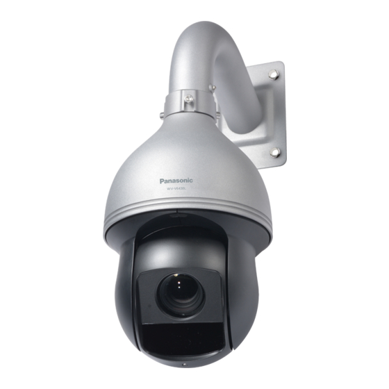
Summary of Contents for Panasonic WV-V6430L
-
Page 1: Network Camera
Network Camera Operating Instructions WV-V6430L Model No Version 1.0.1... -
Page 2: Table Of Contents
Table of Contents Network Connection ··········································································································· 2 Main Interface Introduction ··································································································· 3 Log in ······················································································································ 3 Live Interface ············································································································ 6 Encode Setup ··········································································································· 7 2.3.1. Image Adjustment ···························································································· 8 System Menu ············································································································ 9 Video Window Function Option ····················································································· 9 PTZ Config ····················································································································· 11 PTZ Control ············································································································... - Page 3 7.3.2.2 ONVIF ··································································································· 44 7.3.3. DDNS ·········································································································· 45 7.3.4. IP filter ········································································································· 46 7.3.5. SMTP (Email) ································································································ 47 7.3.6. UPnP ··········································································································· 48 7.3.7. SNMP ·········································································································· 48 7.3.8. Multicast ······································································································· 50 7.3.9. 802.1x ·········································································································· 51 7.3.10. QoS ············································································································· 52 PTZ ······················································································································· 53 7.4.1.
- Page 4 Using the CD-ROM ··········································································································· 85 About the CD launcher ······························································································ 85 Installing Panasonic “IP Setting Software” ····································································· 86 Installing the manuals ······························································································· 86 Installing the Viewer software ····················································································· 87 Configure the network settings of the camera using the Panasonic “IP Setting Software” ········ 87...
- Page 5 Welcome Thank you for purchasing our network camera! This operation manual is designed to be a reference tool for your system. Open the accessory bag to check the items one by one. Depending on the model used, the screens shown in the explanations may differ to the actual camera screens.
-
Page 6: Network Connection
1. Network Connection These series network camera products support the Web access and management via PC. Web includes several modules: monitor channel preview, system configuration, alarm and etc. Follow the steps listed below for network connection. Make sure the network camera has connected to the network properly. •... -
Page 7: Main Interface Introduction
2. Main Interface Introduction Log in Open IE and input network camera address in the address bar. For example, if your camera IP is 192.168.0.10, then input http:// 192.168.0.10 in IE address bar. See Figure 2-1. Input your IP address here Figure 2-1 The login interface is shown as below. - Page 8 If it is your first time to login, you may see the interface window shown as in Figure 2-3 Figure 2-3 Click on “Please click here to download and install the plug-in”. The system pops up warning information to ask you whether run or save this plug-in. See Figure 2-4. Figure 2-4 You must either run or save the file to local and install it.
- Page 9 Figure 2-5 When plug-in installation completes, the installation page closes automatically. The web-end will refresh automatically, and then you can view video captured by the camera. Figure 2-6...
-
Page 10: Live Interface
Live Interface After you logged in, you can see the live monitor window. See Figure 2-7. Figure 2-7 There are three sections: Section 1: Encode setup bar • Section 2: “System” menu • • Section 3: Window function option bar... -
Page 11: Encode Setup
Encode Setup The encode setup interface is shown as in Figure 2-8. Figure 2-8 Refer to the following sheet for detailed information. Parameter Function Menu You can switch “Live” and “Setup” menu. Stream You can switch Main, Sub Stream 1 and 2. The compression under distribution is displayed by Stream change. -
Page 12: Image Adjustment
Image Adjustment You can adjust image quality. See chapter 2.3.1 You can view direction keys, speed, zoom, focus, iris, preset, tour, pan, scan and pattern. Before PTZ operation, please make sure you have properly set PTZ protocol in PTZ setup. See chapter 3. Alarm It moves to an alarm setting screen. -
Page 13: System Menu
System Menu To display the “System” menu, click the [Setup] button as in Figure 2-10. Refer to 7.1 Basic, 7.2 Image/Audio, 7.3 Network, 7.4 PTZ, 7.5 Peripheral, 7.6 Event, 7.7 Storage, 7.8 System, and 7.9 Information for detailed information. Figure 2-10 Video Window Function Option The interface is shown as below. - Page 14 Record For manual record. All records are memorized in [Setup] → [Image] → [Image] → [Path]. When connected to Panasonic’s recorder, record for Sub stream 2 may not work correctly. Audio output Turn on or off audio when you are monitoring.
-
Page 15: Ptz Config
3. PTZ Config Figure 3-1 PTZ Control Here you can view direction keys, speed, zoom, focus, iris, scan, preset, tour, and pattern. See Figure 3-2. Figure 3-2... -
Page 16: Ptz Setting
Parameter Note PTZ supports eight directions: left/right/up/down/upper left/upper right/bottom left/bottom right. Note: PTZ direction When the camera attains its tilt end point with manual operations, the pan automatically rotates the camera so that it does not stop at its tilt end point and enables operations to be continued. - Page 17 It is the accurate positioning function. Please input corresponding Go to horizontal angle, vertical angle and zoom speed and then click “Go to” button to go to a specified position. One unit of the horizontal angle or vertical angle stands for 0.1 degree. ...
-
Page 18: Alarm
4. Alarm Click alarm function, you can see an interface is shown as in Figure 4-1. Here you can set device alarm type and alarm sound setup. Figure 4-1 Refer to the following sheet for detailed information. Type Parameter Function Alarm Type System alarms when VMD alarm occurs. -
Page 19: Playback
5. Playback Web client playback supports video playback and picture playback. Note: Before playback, user shall set storage management as in Chapter 7.7.Storage. • Playback The playback interface is shown as in Figure 5-1. Figure 5-1 There are four sections: •... -
Page 20: Function Of Play
Function of Play 5.1.1. The function of play is shown as in Figure 5-2. Figure 5-2 Parameter Function Play When you see this button, it means pause or not played record. Click on this button, switch to normal play status. Stop Click this button to stop playing. - Page 21 Parameter Function File Type • Select “mp4”, as video playback. Select “jpg” as picture playback. • Data Source Select only SD card. Step1 Click on data in blue, time axis displays record file progress bar in color. While, green represents normal record, yellow represents motion detect record, red represents alarm record, and blue represents manual record.
-
Page 22: Playback Cut
Parameter Function It means records within searched start time and end time on the date. Search Record type is “mp4”, click on the [Download] button and download file to path in Download Chapter 7.2.1.5. Click on the [Back] button to go to calendar interface. Back Playback Cut 5.1.3. -
Page 23: Assistant Function
Parameter Function Click on it, means video in past 24 hours. 24 hours Click on it, means video in past 2 hours. 2 hours Click on it, means video in past 1 hour. 1 hour Click on it, means video in past 30 min. 30 min Assistant Function 5.1.6. -
Page 24: Picture Playback
Picture Playback Select file type as “jpg”, and the system will display the interface shown in Figure 5-10. Figure 5-10 Web client picture playback interface has the following three functions: Parameter Function Play function bar Playback file bar Snapshot type bar Play Function 5.2.1. -
Page 25: Playback File
Playback File 5.2.2. Figure 5-12 Step1 Click on file list , select snapshot file of the date. Step2 Double click on file in list, to play this snapshot. See Figure 5-13. Parameter Function It means all snapshot files within the start time and end time of selected date. Search Click on the [Download] button to download snapshot file to local. -
Page 26: Snapshot Type
Figure 5-13 Snapshot Type 5.2.3. After checking snapshot file type, in file list only display file of selected type. See Figure 5-14. Figure 5-14... -
Page 27: Log Out
6. Log out Click the [Logout] button in Encode setup of “Live” window, the system goes back to the login interface. See Figure 6-1 Figure 6-1... -
Page 28: Setup
7. Setup Basic The [Basic] tab includes the local host setup and the date/time setup. The date and time interface is shown as in Figure 7-1. Figure 7-1 Refer to the following sheet for detailed information. Parameter Function Camera title It is to set device name. -
Page 29: Image/Audio
NTP Port It is to set the time server port. Update Period It is to set the sync periods between the device and the time server. Image/Audio Image/Audio 7.2.1. 7.2.1.1 Image The video bit stream interface is shown as below. See Figure 7-2. Figure 7-2 Refer to the following sheet for detailed information. - Page 30 Bit Rate In VBR, the bit rate here is the max value. In CBR, it is a • fixed value. See reference bit stream for recommended value. I Frame Interval Here you can set the P frame amount between two I frames. The value ranges from 1 to 150.
-
Page 31: Snapshot
Frame rate(FPS) NTSC: 1-30fps., PAL: 1-25fps • The frame rate may vary due to different resolutions. Transmission There are two options: VBR and CBR. Priority Note that you can set video quality in VBR mode. Under MJPEG mode, only CBR is available. Bit Rate In CBR, the bit rate here is the max value. -
Page 32: Overlay
7.2.1.3 Overlay The [Overlay] interface is shown as in Figure 7-4, Figure 7-5, Figure 7-6, Figure 7-7 and Figure 7-8. Figure 7-4 Figure 7-5 Figure 7-6... - Page 33 Figure 7-7 Figure 7-8 Refer to the following sheet for detailed information. Parameter Function Click “Draw” to draw privacy zone in the image preview area. Privacy zone Click “Delete” to delete corresponding privacy zone. Click “Clear” to clear all the privacy zone areas. ...
-
Page 34: Roi
Channel Title Check “Enable” to display channel title in the video monitoring window; check “Disable” not to display. You can use the mouse to drag the channel tile to adjust the position of channel title. See Figure 7-5 Time Title ... -
Page 35: Path
Figure 7-9 Parameters Note Enable Check “Enable”, then it will display the ROI in the video monitoring window; Check “Disable”, then it won’t display. Image Quality Set the image quality of ROI, ranging from 1〜6 (best), default is 6. Able to set area block, max 4 areas. 7.2.1.5 Path The storage path interface is shown as in Figure 7-10. -
Page 36: Audio
7.2.1.6 Audio The [Audio] interface is shown as below. See Figure 7-11. Figure 7-11 Refer to the following sheet for detailed information. Parameter Function Enable Check Enable: the stream is A/V composite stream, otherwise it contains video only. Note: Audio can be enabled only when video is enabled. Compression The compression includes G.711Mu, G.726 and AAC. -
Page 37: Image Adjust
Image adjust 7.2.2. Here you can view device property information. The setups become valid immediately after you set. Figure 7-12 Please refer to the following sheet for detailed information. Parameter Note It can select normal, day or night mode, it can set and check config and effect of corresponding mode after selecting mode. -
Page 38: White Balance (Wb)
7.2.2.1 White Balance (WB) Figure 7-13 Parameter Function White Balance It is to set the white balance mode. It has effect on the general hue of the video. This function is on by default. You can select the different scene mode such as auto, natural, street lamp, outdoor, manual and regional custom to adjust the video to the best quality. -
Page 39: Exposure
7.2.2.2 Exposure Figure 7-14 Parameter Function Auto The video whole brightness can automatically change within Exposure the proper exposure range according to the different environments. The higher the gain max value is, the lower the noise is. Shutter Priority The image overall brightness can auto adjust according to the adjustment shutter range priority according to different scene brightness in normal exposure range. -
Page 40: Backlight
Iris the value range is from 1 to 18. (Aperture Priority/ Manual) It is to set the value of exposure compensation; value range is from 1 to 15. Exposure Comp (Auto/ Shutter Priority/Aperture Priority) It is to set the exposure adjustment speed; the value range is from 1 to 16. Slow Exp (Auto/ Shutter Priority/Aperture Priority) It is to set the maximum level of auto gain from Low/Middle/High. -
Page 41: Day & Night
Parameter Function Mode For the WDR scene, this function can lower the high bright section and enhance the brightness of the low bright section. So that you can view these two sections clearly at the same time. The value ranges from 0 to 100. When you switch the camera from no-WDR mode to the WDR mode, system may lose several seconds record video. -
Page 42: Focus & Zoom
Day&Night It is to set device color and the B/W mode switch. • “Auto”: Device auto select to output the color or the B/W video according to the general bright of the video. • “Color”: Device outputs the color video. “Black &... -
Page 43: Picture
Parameter Note It is to set the steady ability or anti-interference capability of focus, the lower the value is, the steadier it becomes, the higher the value is, the stronger the Sensitivity anti-interference capability becomes. It is to ensure the camera focus clearly when the IR light is enabled. IR Correction Click the button and it will implement lens initialization automatically, at this moment, Lens Init... -
Page 44: Defog
Contrast It is to adjust monitor window contrast. The larger the number, the higher the contrast is. You can use this function when the whole video bright is OK but the contrast is not proper. Note that the video may become hazy if the value is too low. If this value is too high, the dark section may lack brightness while the bright section may over exposure. -
Page 45: Default
Refer to the following sheet for detailed information. Parameter Function Mode • When the “Mode” is set as “Auto”, the system will auto adjust the image definition according to the actual scene.You can select “Low”, “Middle” and “Hight”. • When the “Mode” is set as “Off”, then the defog function is disabled. 7.2.2.8 Default It is to restore camera parameter to factory default setup. - Page 46 The [Profile Management] tab has three modes: “Normal”, “Full Time” and “Schedule”. Parameter Function Profile Management • If you select “Normal”, the video will be configured as normal. If you select “Full Time”, you must select either “Day” or “Night” of [Always •...
-
Page 47: Network
Network TCP/IP 7.3.1. The [TCP/IP] interface is shown as in Figure 7-22. Figure 7-22 Refer to the following sheet for detailed information. Parameter Function Host Name It is to set current host device name. It max supports 32-digit character. Mode There are two modes: Static mode and the DHCP mode. -
Page 48: Connection
Connection 7.3.2. 7.3.2.1 Connection The [Connection] interface is shown as in Figure 7-23. Figure 7-23 Refer to the following sheet for detailed information. Parameter Function Max Connection It is the max Web connection for the same device. The value ranges from 1 to 20. -
Page 49: Ddns
Figure 7-24 DDNS 7.3.3. The [DDNS] interface is shown as in Figure 7-25. The DDNS is to set to connect the various servers so that you can access the system via the server. Go to the corresponding service website to apply a domain name and then access the system via the domain. It works even your IP address has changed. -
Page 50: Ip Filter
Parameter Function Password The password you input to log in the server. Access interval Device sends out alive signal to the server regularly. • You can set interval value between the device and DDNS server here. • IP filter 7.3.4. The [IP Filter] interface is shown as in Figure 7-26. -
Page 51: Smtp (Email)
SMTP (Email) 7.3.5. The [SMTP] interface is shown as in Figure 7-27. Figure 7-27 Refer to the following sheet for detailed information. Parameter Function SMTP Server Input server address and then enable this function. Port Default value is 25. You can modify it if necessary. Anonymity For the server supports the anonymity function. -
Page 52: Upnp
Parameter Function Health Mail Check the box here to enable this function. Update Period (interval) This function allows the system to send out the test email to check the connection is OK or not. Check the box to enable this function and then set the corresponding interval. - Page 53 Figure 7-29 Figure 7-30 Refer to the following sheet for detailed information. Parameter Function SNMP version SNMP V1: system only processes the information of V1. • SNMP V2: system only processes the information of V2. • • SNMP V3: you can set user name and password. There is account security verification when the server wants to connect to the device.
-
Page 54: Multicast
Parameter Function Write Community It is a string. It is a command between the manage process and the proxy process. It defined the authentication, access control and the management relationship between one proxy and one group of the managers. Make sure the device and the proxy are the same. -
Page 55: 802.1X
Figure 7-31 Refer to the following sheet for detailed information. Parameter Function Enable Select to enable multicast function. Multicast Address The range of multicast address of Main Stream, Sub Stream1 and Sub Stream2 is 224.0.0.0 -239.255.255.255. Multicast Port Multicast port. The range is 1025 - 65529. 802.1x 7.3.9. -
Page 56: Qos
7.3.10. The [QoS] interface is shown as below. See Figure 7-33. QoS (Quality of Service) is network security mechanism. It is a technology to fix the network delay and jam problem and etc. For the network service, the quality of service includes the transmission bandwidth, delay, the packet loss and etc. -
Page 57: Ptz
Protocol 7.4.1. 7.4.1.1 Network PTZ Figure 7-34 Step 1 Set PTZ protocol. Step 2 Click “Save” to complete config. Parameter Function Protocol The Private1 can support 80 presets position. The Private3 can support 300 presets position. The default setting is Private3. Function 7.4.2. -
Page 58: Tour
Note: Double click “Preset title” to modify the title to be displayed on the monitoring screen for the preset. Double click “No” to modify preset No. to be registered. Click to delete the preset. Click “Clear” to remove all the preset. 7.4.2.2 Tour Tour can realize auto movement according to the set preset. -
Page 59: Scan
7.4.2.3 Scan Scan means the speed dome scanning back and forth within the left and right limit with a certain speed. Figure 7-37 Step1 Select scan number. Step2 Select scan speed Step3 Click “Set” to control device direction, and click “Set Left Limit” and “Set Right Limit”. Step4 Click “Start”... -
Page 60: Pan
Step1 Select Pattern No. Step2 Click “Set” and click “Start Rec”, then operate the PTZ according to requirrements, and click “Stop Rec” Step3 Click “Start” to start pattern. Step4 Click “Stop” to stop pattern. 7.4.2.5 Pan means the speed dome rotating continuously 360°horizontally with a certain speed. Figure 7-39 Step1 Select pan speed, it is 5 by default. -
Page 61: Idle Motion
Select PTZ speed, it is “Middle” by default. The system will make the PTZ rotate with the speed you just set. 7.4.2.7 Idle Motion Idle motion means the device implementing the behavior which is set in advance when it is not receiving any valid command within the set time. -
Page 62: Time Task
Figure 7-42 Step1 Check “Enable” to enable the function. Step2 Select the powerup motion. Note: When selecting “Auto”, the system will operate the last motion before power off. Step3 Set “Number” except “Auto”. Step4 Click “Save” to complete config. 7.4.2.9 Time Task Time task is to implement relevant movements within the set period. -
Page 63: 7.4.2.10 Ptz Restart
Step3 Select time task action and its corresponding action number. Step4 Set auto home time. Step5 Click “Period setting” and set period of time task on new setup window. Step6 Click “Save”. Auto home time means the time it needs to take to auto recover time task when manually calling PTZ and interrupting time task. - Page 64 Figure 7-45 Click “Default” to set all the default settings for PTZ functions.
-
Page 65: Peripheral
Peripheral IR Light 7.5.1. 7.5.1.1 IR Light You can directly set the mode of IR light if the device is equipped with IR light. Figure 7-46 Step1 It is to set IR light mode according to the actual scene. When the “Mode”... -
Page 66: Event
Event Video Detection 7.6.1. 7.6.1.1 The [VMD] interface is shown as in Figure 7-47. Figure 7-47 Refer to the following sheet for detailed information. Parameter Function Enable You need to check the box to enable VMD function. Working Period Here you can set arm/disarm period. Click on the [Set] button to open period setup menu. - Page 67 Parameter Function Here you can set PTZ movement when alarm occurs. Such as go to preset x when there is an alarm. The event type includes: preset, tour and pattern. Snapshot You need to check the box here so that system can backup VMD snapshot file.
-
Page 68: Tampering
Figure 7-49 Refer to the following sheet for detailed information. Parameter Function Name Default area name includes “Region1”, “Region2”, “Region3”, “Region4” and custom. Sensitivity It is sensitivity of brightness as VMD is more possible to be trigger with high sensitivity. You can set up to four areas. The range is 0 - 100. The recommenced value is 30 - 70. - Page 69 Refer to the following sheet for detailed information. Parameter Function Enable You need to check the box to enable this function. Working Period Video masking function becomes activated in the specified periods. • • There are six periods in one day. Draw a circle to enable corresponding period.
-
Page 70: Audio Detection
Audio Detection 7.6.2. The system will display the [Audio Detection] interface, which is shown in Figure 7-52. Configure info of each parameter according to the actual needs. Refer to the following sheet for more details. Figure 7-52 Parameter Note Enable Input Abnormal Check “Enable Input Abnormal”... - Page 71 Figure 7-53 Refer to the following sheet for detailed information. Parameter Function Enable After enabled, relay activation will work. Relay-in The default is Alarm 1. Working period This function becomes activated in the specified periods. • There are six periods in one day. Draw a circle to enable corresponding •...
-
Page 72: Abnormality
Abnormality 7.6.4. Abnormality includes “No SD Card”, “SD Card Error”, “Capacity Warning”, “Disconnection” and “Illegal Access”. See Figure 7-54 to Figure 7-58. 7.6.4.1 SD Card SD Card includes “No SD Card”, “SD Card Error” and “Capacity Warning”. Note: Device without SD card function does not have the above three statuses. •... -
Page 73: Network
Refer to the following sheet for detailed information. Parameter Function Event Type It includes: No SD Card, SD Card Error and Capacity Warning Enable Check to alarm when SD card is abnormal. Relay out Enable alarm activation function. You need to select alarm output port so that system can activate corresponding alarm device when alarm occurs. -
Page 74: Illegal Access
7.6.4.3 Illegal Access When login password keep been wrong for a few times, unauthorized access alarm occurs. This operation is similar to SD card error. Allow login error times as when it exceeds this limit, user account will be locked. Figure 7-58 Parameter Function... -
Page 75: Storage
Storage Schedule 7.7.1. Before setting up schedule, the user must set the record mode to “Auto” or “Manual”. Note: • If record mode in record control is off, then device will not snapshot according to schedule. 7.7.1.1 Record Schedule Record schedule steps: Step1 Click on the [Record Schedule] tab. -
Page 76: Snapshot Schedule
Step3 Click on the [Save] button, and return to the [Record Schedule] interface. See Figure 7-61. • Green color stands for the general record/snapshot. Yellow color stands for the motion detect record/snapshot. • Red color stands for the alarm record/snapshot. •... -
Page 77: Holiday Schedule
Figure 7-63 Step3 Click on the [Save] button, and return to the [Snapshot Schedule] interface. See Figure 7-64. Green color stands for the general record/snapshot. • Yellow color stands for the motion detect record/snapshot. • Red color stands for the alarm record/snapshot. •... -
Page 78: Destination
Figure 7-65 Step2 Select date to set as holiday. The selected date will be highlighted in green. Step3 Check “Record” and “Snapshot”, and click the [Save] button. System prompts it is successfully saved. Step4 Check “Record Schedule” or “Snapshot Schedule” interface, click the [Setup] button next to Holiday, refer to setup of “Monday”... -
Page 79: Local
Parameter Function It saved in the FTP server. 7.7.2.2 Local The [Local] interface is shown as in Figure 7-67. Here you can view local Micro SD card information. You can also operate the read-only, write-only, hot swap and format operation. Figure 7-67 Click “Read only”... -
Page 80: Record Control
Password Password used to log in FTP server. Remote Directory Store it to the directory of FTP server. Check it and it will store to local SD card when FTP storage abnormity Emergency (Local) occurs. Record Control 7.7.3. The [Record Control] interface is shown as in Figure 7-69. Figure 7-69 Refer to the following sheet for detailed information. -
Page 81: System
System Account (User mng.) 7.8.1. Note: For the character in the following user name or the user group name, 1-32 characters. • The valid string includes: character, number, and underline. Password can be 8~32 characters in number and letter only. User can modify other user’s password. •... -
Page 82: Group
Figure 7-71 Modify user It is to modify the user property, belonging group, password and rights. See Figure 7-72. Modify password It is to modify the user password. You need to input the old password and then input the new password twice to confirm the new setup. - Page 83 Figure 7-73 Add Group It is to add group and set its corresponding rights. Input the group name and then check the box to select the corresponding rights. It includes: “Live”, “Playback”, “Record control” and etc. Figure 7-74 Modify group Click the [Modify group] button.
-
Page 84: Default Reset
Figure 7-75 Default reset 7.8.2. The [Default reset] interface is shown as in Figure 7-76. Note that the system cannot restore some information such as network IP address and Username/Password. Figure 7-76 Import/Export 7.8.3. The [Import/Export] interface is shown as in Figure 7-77. -
Page 85: Auto Maintain
Figure 7-77 Refer to the following sheet for detailed information. Parameter Function Import It is to import the local setup files to the system. Export It is to export the corresponding system setup to your local PC. Auto Maintain 7.8.4. The [Auto Maintain] interface is shown as in Figure 7-78. - Page 86 Important Improper upgrade program may result in device malfunction. • Figure 7-79...
-
Page 87: Information
Information Version 7.9.1. The [Version] interface is shown as in Figure 7-80. Here you can view Software version, Build Date, WEB version and etc. Note that the following information is for reference only. Figure 7-80 7.9.2. Here you can view the system log. See Figure 7-81. Figure 7-81 Refer to the following sheet for log parameter information. -
Page 88: Online User
Parameter Function Search You can select a log type from the drop down list and then click the [Search] button to view the list. You can click the [Stop] button to terminate current search operation. Detailed Information You can select one item in the list to view the detailed information. Clear You can click this button to delete all displayed log files. -
Page 89: Using The Cd-Rom
The Panasonic “IP Setting Software” can be installed on the PC. (→8.2 Installing Panasonic “IP Setting Software””) Settings related to the camera’s network can be set from the Panasonic “IP Setting Software”. (→8.5 Configure the network settings of the camera using the Panasonic “IP Setting Software”) -
Page 90: Installing Panasonic "Ip Setting Software
Installing Panasonic “IP Setting Software” On the CD launcher window, click the [Install] button next to [IP Setting Software] to display the Panasonic “IP Setting Software” installation window. Confirm the following settings before starting the installation. Figure 8-2 Procedure Contents Select the Panasonic “IP Setting Software”... -
Page 91: Installing The Viewer Software
CD-ROM. When using multiple cameras, it is necessary to configure the network settings of each camera independently. If the Panasonic “IP Setting Software” does not work, access the “Network” page from the setup menu of the camera in the browser and perform settings separately. (→7.3 Network) IMPORTANT The “Windows Security Alert”... - Page 92 However, settings can be changed after 20 minutes for cameras in the initial set mode. To start the Panasonic “IP Setting Software”, click the [Run] button next to [IP Setting Software] from the CD launcher menu window, or double-click on the shortcut icon created after installing the software on the PC.
- Page 93 Changing Network Settings When changing settings related to the network settings, such as connection mode, IP address, and subnet mask, click the [Network Settings] button in “IP Setting Software” screen. The “Network Settings” screen is displayed. Enter each item and then click the [Save] button. Figure 8-5 Note •...
Need help?
Do you have a question about the WV-V6430L and is the answer not in the manual?
Questions and answers