
Related Manuals for Winmate IBMH100


Summary of Contents for Winmate IBMH100
-
Page 1: User Manual
M-Series Box PC Intel® Atom™ E3845 IBMH100 User Manual Version 1.1 Document Part Number: 915211171010... -
Page 2: Table Of Contents
USER MANUAL CONTENTS CONTENTS PREFACE ..............................- 4 - ABOUT THIS USER MANUAL ........................- 8 - CHAPTER 1: GENERAL INFORMATION ....................- 10 - 1.1 I ............................ - 10 - NTRODUCTION 1.2 F ............................- 10 - EATURES 1.3 P .......................... - Page 3 USER MANUAL CONTENTS 4.2.3 USB Configuration ........................- 36 - 4.2.4 Chipset ............................. - 38 - 4.2.5 Security ............................ - 41 - 4.2.6 Boot ............................- 43 - 4.2.7 Save & Exit ..........................- 45 - 4.3 U ..................- 47 - SING ECOVERY IZARD TO...
-
Page 4: Preface
USER MANUAL PREFACE PREFACE Copyright Notice No part of this document may be reproduced, copied, translated, or transmitted in any form or by any means, electronic or mechanical, for any purpose, without the prior written permission of the original manufacturer. Trademark Acknowledgement Brand and product names are trademarks or registered trademarks of their respective owners. -
Page 5: Customer Service
USER MANUAL PREFACE Customer Service We provide a service guide as below for any problem by the following steps: First, contact your distributor, sales representative, or our customer service center for technical support if you need additional assistance. You need to prepare the following information before you call: ... - Page 6 USER MANUAL PREFACE Advisory Conventions Four types of advisories are used throughout the user manual to provide helpful information or to alert you to the potential for hardware damage or personal injury. These are Notes, Important, Cautions, and Warnings. The following is an example of each type of advisory.
-
Page 7: Safety Precautions
USER MANUAL PREFACE Safety Precautions WARNING! Always completely disconnect the power from OPS module whenever you work with the hardware. Do not make connections while the power is on. Sensitive electronic components can be damaged by sudden power surges. CAUTION Always ground yourself to remove any static charge before touching the CPU card. -
Page 8: About This User Manual
ABOUT THIS USER MANUAL ABOUT THIS USER MANUAL This User Manual provides information about using the Winmate® M-Series Box PC with Intel® Atom™ E3845 processor. The documentation set for the M -Series Box PC provides information for specific user needs, and includes: ... -
Page 9: Chapter 1: General Information
USER MANUAL CHAPTER 1 GENERAL INFORMATION GENERAL INFORMATION This chapter includes IBMH100 Industrial PC background information. - 9 -... -
Page 10: Introduction
1.1 Introduction Thank you for choosing the Winmate® IBMH100 M-Series Box PC. This is versatile and cost-effective solution for your industrial needs. Intel® Atom™ E3845 1.91 GHz processor onboard with fanless cooling system assures steady performance and silent functioning. -
Page 11: Package Contents
CHAPTER 1 GENERAL INFORMATION 1.3 Package Contents Carefully remove the box and unpack your IBMH100 Industrial PC. Please check if all the items listed below are inside your package. If any of these items are missing or damaged contact us immediately. -
Page 12: Physical Description
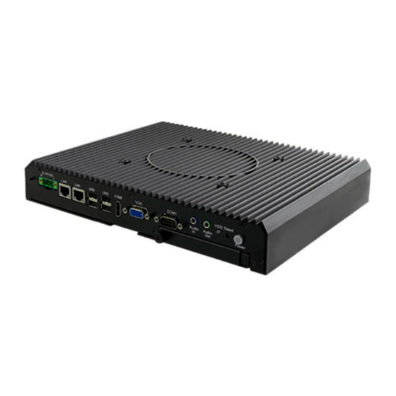
CHAPTER 1 GENERAL INFORMATION 1.4 Physical Description This section explains physical characteristics of the IBMH100 M-Series Box PC. 1.4.1 Connector Placement and Dimensions The module front panel consists of 2.5” SSD Bay, power/reset buttons, audio jacks, two RJ45 connectors, HDMI and VGA outputs, and four USB2.0 ports. -
Page 13: Chapter 2: Hardware Installation
USER MANUAL CHAPTER 2 HARDWARE INSTALLATION HARDWARE INSTALLATION This chapter provides information on how to use jumpers and connectors on the motherboard, and the IBMH100 Industrial PC hardware specifications and installation instruction. - 13 -... -
Page 14: Connector Pin Assignments
USER MANUAL CHAPTER 2 HARDWARE INSTALLATION CHAPTER 2: HARDWARE INSTALLATION This chapter provides information on external connectors on IBMH100 M-Series Box PC and hardware specifications and installation instruction. 2.1 Connector Pin Assignments This section includes I/O side connectors and its pinouts. -
Page 15: Hdmi Output Connector
Signal Name Pin № Pin № Data- Data+ 2.1.6 VGA Output Connector The IBMH100 has VGA connector (D-Sub 15pin Female). Use VGA cable to connect the display to the PC system. Pin № Signal Name Pin № Signal Name GREEN... -
Page 16: Lan Connector
USER MANUAL CHAPTER 2 HARDWARE INSTALLATION 2.1.7 LAN Connector The IBMH100 equipped with one RJ45 10/100/1000 Mbps Ethernet interface for connecting to the internet. Pin № Signal Name Pin № Signal Name TX1+ TX1- TX2+ TX2- TX3+ TX3- TX4+ TX4-... -
Page 17: Hardware Installation
This section explains how to replace HDD/SDD, install PCI Card/ RAM/ Internal SSD, and replace fuses on the IBMH100 M-Series Box PC. WARNING! Switch off the power and unplug the power cord. Each time the IBMH100 M-Series Box PC is serviced, users should be aware of this condition. 2.2.1 Hard Disk Replacement Remove the hard disk: 1. -
Page 18: Pci Card, Ram, Internal Ssd, Fuse Replacement
USER MANUAL CHAPTER 2 HARDWARE INSTALLATION 2.2.2 PCI Card, RAM, Internal SSD, Fuse Replacement To replace the PCI card, RAM, Internal SSD, Fuse: 1. Turn the device right-side up, with the back toward you. 2. Loosen two Philips M3x5 screws that secure side cover. 3. - Page 19 USER MANUAL CHAPTER 2 HARDWARE INSTALLATION Reverse this procedure to install the PCI card/ RAM/ Internal SSD/ Fuse. - 19 -...
-
Page 20: Chapter 3: Driver Installation
USER MANUAL CHAPTER 3 DRIVER INSTALLATION DRIVER INSTALLATION This chapter provides driver installation instructions. - 20 -... -
Page 21: Chipset Driver
USER MANUAL CHAPTER 3 DRIVER INSTALLATION CHAPTER 3: DRIVER INSTALLATION This chapter provides driver installation instructions. 3.1 Chipset Driver Step 1 Insert the CD that comes with the motherboard. Open the file document “Chipset Driver” and click “infinst_auto.exe” to install driver. - 21 -... - Page 22 USER MANUAL CHAPTER 3 DRIVER INSTALLATION Step 2 Click Next to continue. Step 3 Click Yes to agree the license terms. - 22 -...
- Page 23 USER MANUAL CHAPTER 3 DRIVER INSTALLATION Step 4 Click Next to install the driver. Step 5 Software setup progress window will appear, click Next to continue. Step 6 Click “Yes, I want to restart this computer now” to finish the installation. - 23 -...
-
Page 24: Graphics Driver
USER MANUAL CHAPTER 3 DRIVER INSTALLATION 3.2 Graphics Driver Step 1 Insert the CD that comes with the motherboard. Open the file document “Graphics Driver” and click Setup to execute the setup. Step 2 Setup Welcome Window will appear, click Next to continue the process. Step 3 Carefully read the license terms and click Yes to agree. -
Page 25: Audio Driver
USER MANUAL CHAPTER 3 DRIVER INSTALLATION 3.3 Audio Driver The ALC886 series are high-performance 7.1+2 channel high definition audio codecs that provide ten DAC channels for simultaneous support of 7.1 sound playback, plus 2 channels of independent stereo sound output (multiple streaming) through the front panel stereo outputs. -
Page 26: Intel Mbi Driver (Windows 8)
USER MANUAL CHAPTER 3 DRIVER INSTALLATION 3.4 Intel MBI Driver (Windows 8) Step 1 Insert the CD that comes with the motherboard. Open the file document “MBI” and click “Setup.exe” to install the driver. Step 2 Welcome to the setup program window will appear, click Next to start the installation. -
Page 27: Intel Trusted Engine Interface (Intel Txe) Driver
USER MANUAL CHAPTER 3 DRIVER INSTALLATION 3.5 Intel Trusted Engine Interface (Intel TXE) Driver Step 1 Insert the CD that comes with the motherboard. Open the file document “TXE” and click “Setup TXE.exe” to install the driver. Step 2 Welcome to the setup program window will appear, click Next to start the installation. -
Page 28: Intel Network Connections
USER MANUAL CHAPTER 3 DRIVER INSTALLATION 3.6 Intel Network Connections User must confirm the type of operating system is being used before installing Intel Network Connections. Follow the steps below to complete the installation. Step 1 Click “PROWin64.exe” Step 2 Click Yes to start the installation. Step 3 Welcome window will appear, click Next to install the driver. -
Page 29: Usb 3.0 Driver (Windows 7)
USER MANUAL CHAPTER 3 DRIVER INSTALLATION 3.7 USB 3.0 Driver (Windows 7) NOTE: If your operation system is Windows Embedded 8.1 Industry or Windows Embedded 8 Standard, you should skip the USB 3.0 driver installation. You need to install the Intel® USB 3.0 extensible Host Controller driver to enable the function. -
Page 30: Chapter 4: Ami Uefi Bios Setup
USER MANUAL CHAPTER 4 AMI UEFI BIOS SETUP AMI UEFI BIOS SETUP BIOS Setup Utility is a program for configuration basic Input / Output system settings of the computer for optimum use. This chapter provides information on how to use BIOS setup, its functions and menu. -
Page 31: When And How To Use Bios Setup
USER MANUAL CHAPTER 4 AMI UEFI BIOS SETUP CHAPTER 4: AMI UEFI BIOS SETUP BIOS Setup Utility is a program for configuration basic Input / Output system settings of the computer for optimum use. This chapter provides information on how to use BIOS setup, its functions and menu. -
Page 32: Bios Functions
USER MANUAL CHAPTER 4 AMI UEFI BIOS SETUP 4.2 BIOS Functions BIOS Navigation Keys BIOS navigation keys for keyboard control are listed below. The following keys are enabled during Power-On Self-Test (POST): Function Enters the BIOS setup menu. Display the boot menu. Lists all bootable devices that are connected to the system. -
Page 33: Main Menu
USER MANUAL CHAPTER 4 AMI UEFI BIOS SETUP 4.2.1 Main Menu When you enter BIOS setup, the first menu that appears on the screen is the main menu .It contains the system information including BIOS version, processor RC version, system language, time, and date. Immediately after the [DEL] key is pressed during startup, the main BIOS setup menu appears: BIOS Setting Description... -
Page 34: Advanced Menu
USER MANUAL CHAPTER 4 AMI UEFI BIOS SETUP 4.2.2 Advanced Menu The advanced menu also uses to set configuration of the CPU and other system devices. There are sub menus on the left frame of the screen. IMPORTANT: Handle advanced BIOS settings page with caution. Any changes can affect the operation of your computer. - Page 35 USER MANUAL CHAPTER 4 AMI UEFI BIOS SETUP BIOS Setting Description Setting options Effect Configures ACPI ACPI Settings Enter Opens submenu settings Configures SMART SMART Settings Enter Opens submenu settings Configures System Super IO Super IO Chip Enter Opens submenu Configuration parameters Monitor hardware...
-
Page 36: Usb Configuration
USER MANUAL CHAPTER 4 AMI UEFI BIOS SETUP 4.2.3 USB Configuration - 36 -... - Page 37 USER MANUAL CHAPTER 4 AMI UEFI BIOS SETUP BIOS Setting Description Setting options Effect Will keep USB devices available Disable only for EFI Legacy USB User can enable or Support disable USB port. applications. Enable all the USB Enable devices User can enable or Enable USB 3.0 is enable...
-
Page 38: Chipset
USER MANUAL CHAPTER 4 AMI UEFI BIOS SETUP 4.2.4 Chipset 4.2.4.1 Chipset – North Bridge Parameters - 38 -... - Page 39 USER MANUAL CHAPTER 4 AMI UEFI BIOS SETUP BIOS Setting Description Setting options Effect Provides onboard Intel IGD graphics-related Enter Opens submenu Configuration configuration options. Configures IGD – IGD – LCD Control Enter Opens submenu LCD setting Provides power Graphic Power saving Management configuration...
- Page 40 USER MANUAL CHAPTER 4 AMI UEFI BIOS SETUP BIOS Setting Description Setting options Effect Configures onboard Disable Disables this function Azalia HD Audio audio function. Enable Enables this function Enable / Disable this USB 2.0(EHCI) function Provides user with Enable / Disable this configuration options for USB Port 0 function...
-
Page 41: Security
USER MANUAL CHAPTER 4 AMI UEFI BIOS SETUP 4.2.5 Security Allows user to configure an administration or user password, user must enter the administrator or user password at system startup and when entering BIOS setup. BIOS Setting Description Setting options Effect Displays whether or Administrator... - Page 42 USER MANUAL CHAPTER 4 AMI UEFI BIOS SETUP 4.2.5.1 Security – Secure Boot Menu BIOS Setting Description Setting options Effect Disables this Disable Displays the function Secure Boot current boot state. Enables this Enable function Disables this Allows user to Disable function Secure Boot Mode...
-
Page 43: Boot
USER MANUAL CHAPTER 4 AMI UEFI BIOS SETUP 4.2.6 Boot - 43 -... - Page 44 USER MANUAL CHAPTER 4 AMI UEFI BIOS SETUP BIOS Setting Description Setting options Effect Allows user to configure the Setup Prompt number of seconds Set the prompt Enter Timeout to stay in BIOS timeout setup prompt screen. Enables or disables Remains On NumLock feature on Boot NumLock...
-
Page 45: Save & Exit
USER MANUAL CHAPTER 4 AMI UEFI BIOS SETUP 4.2.7 Save & Exit - 45 -... - Page 46 USER MANUAL CHAPTER 4 AMI UEFI BIOS SETUP BIOS Setting Description Setting options Effect This saves the Enter <Yes> Saves the changes changes to the Save Changes and CMOS and exits the Return to the BIOS Exit Esc <No> BIOS Setup Setup Main Menu program.
-
Page 47: Using Recovery Wizard To Restore Computer
USER MANUAL CHAPTER 4 AMI UEFI BIOS SETUP 4.3 Using Recovery Wizard to Restore Computer Note: Before starting the recovery process, make sure to backup all user data. The data will be lost after the recovery process. To enable quick one-key recovery procedure: ... -
Page 48: How To Enable Watchdog
USER MANUAL CHAPTER 4 AMI UEFI BIOS SETUP 4.4 How to Enable Watchdog To enable Watchdog, you need to download Winmate Watchdog utility. Find more information on Watchdog in “Watchdog Guide” that you can download from Winmate Download Center or File Share. - Page 49 USER MANUAL CHAPTER 4 AMI UEFI BIOS SETUP Example: Every 10 min watchdog will monitor the system, in case any error occurs the system will restart automatically when the countdown time reaches 0. Every 9 min watchdog timer will be reset to 10 min. Settings Description The system automaticity restarts when this...
-
Page 50: Chapter 5: Technical Support
USER MANUAL CHAPTER 5 TECHNICAL SUPPORT TECHNICAL SUPPORT This chapter contains directory to technical support. - 50 -... -
Page 51: Software Developer Support
This chapter includes technical support documents and software developing kit (SDK). If any problem occurs fill in problem report form enclosed and immediately contact us. 5.1 Software Developer Support Winmate provides the following development kits (SDK) for IBMH100 M-Series Box PC: Item File Type Description Watchdog SDK & AP... -
Page 52: Problem Report Form
USER MANUAL CHAPTER 5 TECHNICAL SUPPORT 5.2 Problem Report Form M-Series Box PC (Modular Design) Customer name: Company: Tel.: Fax: E-mail: Date: Product Serial Number: ___________________________________________________________________ Problem Description: Please describe the problem as clearly as possible. Detailed description of the occurred problem will allow us to find the best solution to solve the problem as soon as possible. -
Page 53: Appendix A: Product Specifications
USER MANUAL APPENDIX A PRODUCT SPECIFICATIONS PRODUCT SPECIFICATIONS This section includes IBMH100 technical specifications. Appendix - 53 -... - Page 54 USER MANUAL APPENDIX A PRODUCT SPECIFICATIONS APPENDIX A: PRODUCT SPECIFICATIONS Hardware Specifications Model Name IBMH100 Intel® Atom™ E3845 Processor; 2M Cache up to 1.91 GHz BIOS AMI UEFI BIOS Graphic Chipset Intel® HD graphics System Memory SODIMM DDR3L-1600 4GB, Option up to 8GB (2 slots)
- Page 55 USER MANUAL APPENDIX A PRODUCT SPECIFICATIONS Software Support The following drivers are available for the IBMH100 PRO Series Industrial PC: Item Driver Windows 7 Windows 8 Windows 10 Chipset Driver ☑ ☑ ☑ Graphics Driver ☑ ☑ ☑ Audio Driver ☑...
- Page 56 Winmate Inc. 9F, No.111-6, Shing-De Rd., San-Chung District, New Taipei City 24158, Taiwan, R.O.C Tel: 886-2-8511-0288 Fax: 886-2-8511-0211 Email: sales@winmate.com.tw Official website: www.winmate.com...
Need help?
Do you have a question about the IBMH100 and is the answer not in the manual?
Questions and answers