Sign In
Upload
Manuals
Brands
MR Manuals
Controller
TAPCON 250
User Manuals: MR TAPCON 250 Voltage Regulator
Manuals and User Guides for MR TAPCON 250 Voltage Regulator. We have
3
MR TAPCON 250 Voltage Regulator manuals available for free PDF download: Operating Instructions Manual, Supplement Manual
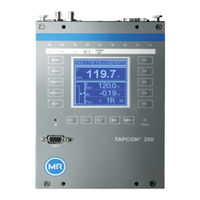
MR TAPCON 250 Operating Instructions Manual (216 pages)
Voltage regulator
Brand:
MR
| Category:
Controller
| Size: 10 MB
Table of Contents
Table of Contents
3
Introduction
8
Manufacturer
8
Completeness
8
Safekeeping
8
Notation Conventions
8
Hazard Communication System
8
Information System
10
Instruction System
10
Typographic Conventions
11
Safety
12
Appropriate Use
12
Inappropriate Use
13
Fundamental Safety Instructions
13
Personnel Qualification
15
Personal Protective Equipment
16
Security
18
General
18
Operation
18
Commissioning
18
Communication Interfaces
19
Encryption Standards
21
Product Description
22
Scope of Delivery
22
Function Description of the Voltage Regulation
22
Performance Features
23
Design
25
Display, Operating Elements and Front Interface
26
Leds
27
ISM® Assemblies
28
Connections and Fuses
37
Nameplate
38
Safety Markings
38
Connection Diagram and Grounding Screw
38
Visualization
39
Packaging, Transport and Storage
46
Suitability, Structure and Production
46
Markings
46
Transportation, Receipt and Handling of Shipments
46
Storage of Shipments
47
Mounting
48
Preparation
48
Minimum Distances
49
Assembly Variants
49
Flush Panel Mounting
49
Fastening the Cap Rail
51
Installing Modules in the Control Cabinet
52
Connecting the Device
56
Cable Recommendation
56
Electromagnetic Compatibility
57
Connecting Cables to the System Periphery
60
Connecting the CAN Bus
60
Connecting SCADA
61
Wiring Voltage Measurement/Current Measurement UI
62
Wiring the MC 2-2/SW3-3 Assembly
63
Wiring Analog Inputs AI
66
Wiring Digital Inputs DI
67
Wiring Digital Outputs DO
68
Wiring Resistor Contact Series
68
Connecting the Power Supply
68
Performing Tests
70
Initial Steps
71
Establishing Connection to Visualization
71
Commissioning
74
Commissioning Wizard
74
Performing Tests
74
Ground Test
75
Performing a Dielectric Test
75
Function Tests
77
Checking Measured Values and Status of Digital Inputs and Outputs
77
Testing the Device Control Function
77
Checking Parallel Operation
79
Operation
84
System
84
General
84
Configuring the Network
86
Setting the Device Time
87
Setting the Screensaver
88
Configuring Syslog
89
Scada
91
Setting the Measured Value Recorder
97
Linking Signals and Events
98
Configuring Analog Inputs
106
Configuring Digital Inputs and Outputs
109
Event Management
110
User Administration
112
Hardware
112
Software
112
Import/Export Manager
112
Power Grid
117
Transformer Data
117
Voltage Monitoring
123
Current Monitoring
125
Power Monitoring
127
Power Flow Monitoring
129
Monitoring Settings
131
TAPCON® 2Xx Retrofit
131
On-Load Tap-Changer Regulator
134
Voltage Regulation
134
Line Drop Compensation
143
Parallel Operation
145
U Bandwidth Monitoring
153
On-Load Tap-Changer
155
Tap Position Monitoring
155
Target-Tap-Position Operation
160
Information about the On-Load Tap-Changer
161
OLTC Data
161
U Bandwidth Monitoring
163
Displaying the Minimum and Maximum Tap Position
165
Motor-Drive Unit and Control Cabinet
166
Control of the Motor-Drive Unit
166
Setting the Switching Pulse for Controlling the Motor-Drive Unit
166
Maintenance and Care
172
Cleaning the Device
172
Maintenance
172
Fault Elimination
173
General Faults
173
No Regulation in AUTO Mode
173
Unwanted On-Load Tap-Change Operation
174
Human-Machine Interface
174
Incorrect Measured Values
175
Parallel Operation Faults
176
Tap Position Capture Incorrect
177
Other Faults
177
Disposal
179
Technical Data
180
TC250 Technical Data
180
Display Elements
180
Materials
180
Dimensions
180
Voltage Supply
180
Voltage Measurement and Current Measurement
181
Ambient Conditions
182
Standards and Directives
182
ISM® Assemblies Technical Data
184
System Networking COM-ETH
184
Central Processing Unit
184
System Networking BES
186
Power Supply PS
187
G1 Power Supply
187
Voltage Measurement U 3
196
Scada/Communication Interfaces
198
Tap Position Capture / Resistor Contact Series
199
Connection Diagrams
200
Tc250_Final_Basic.pdf
200
Tapcon® 250 Pro
207
Tapcon® 250 Expert
211
Glossary
213
Advertisement
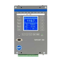
MR TAPCON 250 Operating Instructions Manual (158 pages)
Voltage Regulator
Brand:
MR
| Category:
Controller
| Size: 6 MB
Table of Contents
Table of Contents
3
1 Introduction
8
Manufacturer
8
Completeness
8
Safekeeping
8
Notation Conventions
8
Hazard Communication System
8
Information System
10
Instruction System
10
Typographic Conventions
11
2 Safety
12
Appropriate Use
12
Fundamental Safety Instructions
12
Personnel Qualification
14
Personal Protective Equipment
15
3 Product Description
17
Scope of Delivery
17
Function Description of the Voltage Regulation
17
Performance Features
17
Operating Modes
18
Hardware
20
Name Plate
21
Operating Controls
23
Display Elements
25
Serial Interface
26
Assemblies
26
4 Packaging, Transport and Storage
28
Packaging
28
Purpose
28
Suitability, Structure and Production
28
Markings
28
Transportation, Receipt and Handling of Shipments
29
Storage of Shipments
30
5 Mounting
31
Mounting Device
31
Connecting Device
32
Cable Recommendation
32
Electromagnetic Compatibility
33
Information about Laying Fiber-Optic Cable
36
Connecting Cables to the System Periphery
37
Wiring Device
37
Checking Functional Reliability
44
6 Commissioning
46
Function Tests
46
Checking Control Functions
46
Checking Additional Functions
48
Setting Parameters
51
Setting the Language
51
Setting Date and Time
51
Setting Further Parameters
52
7 Operation
55
General
55
Setting Device ID
55
Setting the Baud Rate
56
Setting the Voltage Display Kv/V
56
Setting Current Display Unit
57
Setting the Switching Pulse Time
57
Setting the Consumption Interval
60
Setting Motor Runtime Monitoring
60
Setting the Behavior in the Event of Negative Active Power Flow
62
Defining the Signal Type
62
Key Lock
63
Normset
64
Control Parameters
66
Setting Desired Value 1
68
Analog Setting of the Desired Value (Optional)
69
Bandwidth
72
Setting Voltage Balance
75
Setting Delay Time T1
75
Setting Control Response T1
76
Setting Delay Time T2
77
Limit Values
78
Setting Undervoltage Monitoring V
78
Setting Overvoltage Monitoring V
81
Activating/Deactivating Function Monitoring
83
Setting Hunting Alarm Limit
83
Compensation
84
R&X Compensation
84
Z Compensation
87
Transformer Data
88
Setting the Phase Difference for the Current Transformer/Voltage Transformer
89
Setting the Primary Transformer Voltage
93
Setting the Secondary Transformer Voltage
93
Setting Primary Transformer Current
94
Configurable Inputs and Outputs
94
Linking Inputs with Functions
94
Setting User-Defined Collective Message
96
Parallel Operation
96
Assigning CAN Bus Address
97
Assigning a Parallel Operation Group
98
Selecting Parallel Operation Method
98
Setting Delay Time for Parallel Operation Error Messages
101
Setting the Follower Tapping Direction
102
Activating/Deactivating Parallel Operation
103
Setting the Behavior in the Event of CAN Bus Error
103
LED Selection
104
Memory
104
Setting Undervoltage Threshold
105
Setting Overvoltage Threshold
106
Setting Time Difference of Average Value Interval
107
Setting Event Memory Size
107
Time Plotter
110
Communication Interface
116
Selecting the Communication Protocol
116
Selecting Communication Port
117
Selecting Communication Baud Rate
117
Assigning Network Address
118
Assigning TCP Port
118
Setting Fiber-Optic Cable Transmission Behavior
119
Setting CI Address
119
Setting SCADA Master Address
120
Enabling Unsolicited Messages
121
Setting Number of Attempts to Transmit Unsolicited Messages
121
Timeout for Application Confirm Responses
122
Setting Transmission Delay Time for RS485 Interface
122
Tap Positions
123
Analog Tap Position Capture (Optional)
123
Tap Position Output
125
Permitted Tap Positions
126
Tap-Position Indication
127
Displaying Information about Device
128
Displaying the Info Screen
128
Displaying Measured Values
128
Carrying out LED Test
129
Display of the IO Status
130
Displaying Status of the AI Card
130
Displaying Status of the CI Card
130
Resetting Parameters
131
Displaying Real-Time Clock
131
Displaying Parallel Operation
131
Displaying Data on CAN Bus
132
Displaying Measured Value Memory
133
Displaying Peak Memory
133
Displaying the Operations Counters
134
Displaying Upcoming Messages
134
Display of the Consumption
135
8 Fault Elimination
136
No Regulation in AUTO Mode
136
Unexplained Tap Change
137
Man-Machine Interface
137
Incorrect Measured Values
137
Parallel Operation Faults
138
Customized Gpis/Gpos
139
General Faults
139
Other Faults
140
9 Disposal
141
10 Overview of Parameters
142
11 Technical Data
147
Display Elements
147
Voltage Supply
147
Voltage Measurement and Current Measurement
147
Digital Inputs and Outputs
148
Analog Inputs and Outputs (AI Module)
149
System Networking (CI Module)
150
Dimensions and Weight
150
Ambient Conditions
152
Electromagnetic Compatibility
152
Environmental Durability Tests
152
Mechanical Stability
153
Glossary
154
List of Key Words
155
MR TAPCON 250 Supplement Manual (20 pages)
Voltage Controller
Brand:
MR
| Category:
Controller
| Size: 3 MB
Table of Contents
Table of Contents
3
1 Introduction
4
Manufacturer
4
Subject to Change Without Notice
4
Completeness
4
Supporting Documents
4
Safekeeping
5
2 Safety
6
General Safety Information
6
Appropriate Use
6
Inappropriate Use
6
Personnel Qualification
7
Operator's Duty of Care
7
3 Product Description
8
4 Mounting
9
Installing the Adapter Panel
9
Cable Recommendation
9
Electromagnetic Compatibility
10
Connecting the Adapter Panel
10
5 Technical Data
16
Advertisement
Advertisement
Related Products
MR tapcon 240
MR TAPCON 260
MR TAPCON 230
MR tapcon 230 pro
MR TAPCON 230 basic
MR TAPCON 230 AVT
MR TAPCON 230 VC
MR TAPCON
MR TAPCON 230 Expert
MR TAPCON LV
MR Categories
Industrial Equipment
Controller
Measuring Instruments
Thermometer
Industrial Electrical
More MR Manuals
Login
Sign In
OR
Sign in with Facebook
Sign in with Google
Upload manual
Upload from disk
Upload from URL