
Related Manuals for Polimaster PM1621M


Summary of Contents for Polimaster PM1621M
- Page 1 X-RAY AND GAMMA RADIATION PERSONAL DOSIMETER РМ1621M (PM1621MA) OPERATING MANUAL...
-
Page 2: Table Of Contents
CONTENTS 1 DESCRIPTION AND OPERATION OF THE INSTRUMENT.....5 1.1 Application of the instrument............5 1.2 Delivery kit..................6 1.3 Specifications ..................7 1.4 Design and theory of operation ............12 2 USE OF THE INSTRUMENT .............16 2.1 General guidelines ................16 2.2 Safety instructions................16 2.3 Preparation for use................16 2.4 Use of the instrument ..............16 3 MAINTENANCE.................26 4 TROUBLESHOOTING...............27... - Page 3 This manual is intended to describe the design, operation and use of the X-ray and gamma radiation personal dosimeter PM1621M (PM1621MA) (hereinafter referred to as the device or instrument). The Operating Manual includes the general description, specifications of the instrument, as well as other information necessary for the proper operation of the instrument and understanding of device capabilities.
-
Page 4: Description And Operation Of The Instrument
1 DESCRIPTION AND OPERATION OF THE INSTRUMENT 1.1 Application of the instrument The PM1621M (PM1621MA) X-ray and gamma radiation dosimeter is designed to provide: - continuous measurement of the personal dose equivalent (hereinafter referred to as dose equivalent or DE) of external gamma and X-ray (hereinafter photon) radiation Н... -
Page 5: Delivery Kit
1.2 Delivery kit 1.2.1 Delivery kit of the instrument is specified in the table 1.1. Table 1.1 Item Quantity, pcs. X-ray and gamma radiation dosimeter РМ1621М (PM1621MA) CD Disk with “System of Data Collection and Processing for the 1621/1603/1604 Devices” software Operating manual Package Alkaline AA-type battery (РANASONIC POWER LINE... -
Page 6: Specifications
1.3 Specifications Operating mode: - indication of photon radiation DER; - indication of photon radiation DE; - indication of the instrument’s number; - PC data exchange; - search; - indication of the audible alarm; - indication of the vibration alarm; - set mode;... - Page 7 Discreteness of DE accumulation time indication 1 h. 7 The instrument provides inputting, storage in a non-volatile memory and continuous control of two threshold DER and DE levels within the whole measurement range. When the preset first and second DER and DE alarm threshold levels are exceeded the instrument produces audible, vibration and visual (blinking red LED) signals.
- Page 8 11 Maximum permissible additional relative error of DER measurement: - at temperature variations from minus 40 ±10 %; to plus 60°С - at relative humidity of ambient air 98 % ±10 %; at 35 °С - at power voltage variations from nominal value to limiting voltage values ±...
- Page 9 2) read-out of the following information from the instrument to PC: - instrument’s parameters; - DER history and DE accumulation (date, time, event, value); - DE (DER) values at the moment of exceeding the preset thresholds as well as time, date and month of exceeding the preset thresholds;...
- Page 10 - average full operating time no less than 20000 h; - average service life no less than 10 years - average time of recovery no more than 60 min. N o t e – For additional information about instrument, please visit www.polimaster.com.
-
Page 11: Design And Theory Of Operation
1.4 Design and theory of operation 1.4.1 The instrument comprises the following main blocks and modules: radiation detector; microprocessor; LCD; secondary power supply; IR-transceiver; and non-volatile memory. Backlight Control Audible driver buttons signal Radiation detector High voltage power supply of temperature Microprocessor compensaton Secondary... - Page 12 The PM1621M is provided with a clip and may be fasten to the belt. The clip may be removed using a screwdriver (see Fig.1.3). A carrying pouch is also available as an option.
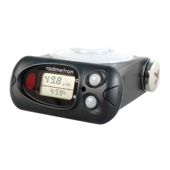
- Page 13 Figure 1.2 – General overview of the instrument...
- Page 14 Figure 1.3 - The PM1621M with a removable clip...
-
Page 15: Use Of The Instrument
2 USE OF THE INSTRUMENT 2.1 General guidelines When you receive the device after purchase please check the delivery kit and confirm proper operation of the device in all the operation modes as outlined in sections 2.4.3 to 2.4.5. Protect the device from shocks and mechanical damages. Avoid exposing the device to hostile environments, organic solvents and open fire. - Page 16 - DE and DER accumulation history; - the preset DER and DE thresholds. When using the instrument in a temperature range from -40°С up to –20 С the device provides performance of the dosimetric functions without displaying the result of measurement on LCD.
- Page 17 2.4.3 DER indication mode In the DER mode (figure 2.1) the following values appear on the LCD: - DER (µSv/h, mSv/h, Sv/h); - DER on the analogue scale in a logarithmic gauge (seven segments); - coefficient of variation in percents; - averaging time of DER values (Range of the averaging time indication is from 1 up to 2999 s.
- Page 18 Inputting the DER (DE) threshold levels into the memory This procedure can be performed in the DER (DE) measurement mode as well as in of data transmission to PC mode. DER (DE) thresholds are input during DER (DE) indication on the LCD. Enter the set mode by pressing and holding the SET button (Figures 2.2, 2.3).
- Page 19 - Choose the mode of data transmission to PC using the MODE button; - Press and release the LIGHT/SET button for PC link startup through IR channel; - Perform readout of the dosimeter’s information following the program’s instructions. 2.4.7.3 Permission or prohibition of the following operating modes (parameters) of the dosimeter: - DER indication;...
- Page 20 2.4.9 Audible alarm indication mode In the audible alarm indication mode (Fig. 2.1) the instrument provides the following functions: - turn on/off the audible alarm; - indication of turning ON/OFF of the audible alarm; - sound pressure level control (Fig. 2.4) and indication in the analog (scale) and digital formats (from 1 to 4);...
- Page 21 Figure 2.1 - Choice of operating mode (indication) of the instrument...
- Page 22 Figure 2.2 - Setting the DE threshold values...
- Page 23 DER indication mode press and hold SET button (for 5s) First DER Second DER threshold threshold flashing flashing threshold number threshold number press press flashing button flashing button press flashing press button flashing button press press button flashing button flashing press button press...
- Page 24 Figure 2.4 – Audio control mode (control of the sound volume)
-
Page 25: Maintenance
3 MAINTENANCE 3.1 Maintenance involves preventive services, battery replacement and regular performance check (according to 2.4.3 - 2.4.5). 3.2 Preventive services include external examination, dusting and decontamination in the event of radioactive contamination. For decontamination wipe the case of the instrument using a cloth wetted with ethanol. 3.3 Battery replacement: - unscrew and remove the cover of the battery compartment;... -
Page 26: Troubleshooting
4 TROUBLESHOOTING The list of possible problems and their solutions are specified in the table 4.1. Table 4.1 Problem Possible cause Solution 1 The LCD indicates “bAt” Battery discharge Replace the battery message 2 No indications on the LCD Battery discharge Replace the battery Battery is inserted Insert the battery correctly... -
Page 27: Storage And Shipping
5 STORAGE AND SHIPPING 5.1 Packaged devices may be shipped by any method of closed transport at the air temperature from -50 °C to +50 °. 5.2 Packaged devices should be secured during transport. 5.3 When carried by sea, packaged devices should be sealed in plastic bags with silicagel. -
Page 28: Warranty
6 WARRANTY 6.1 The manufacturer guaranties that the device meets the requirements of Technical Conditions provided that the customer will observe the guidelines of its use, shipping and storage described in this manual. 6.2 The warranty period of use is 18 months from the date of sale. 6.3 Warranty and after-warranty repair is carried out by the manufacturer or the institutions that have a permission of the manufacturer. -
Page 29: Attachment A Overall Dimensions. Effective Center Of The Detector
ATTACHMENT A (reference) OVERALL DIMENSIONS, EFFECTIVE CENTER OF THE INSTRUMENT DETECTOR 72 mm 35 mm 15 mm Graduation direction (to radiation source) Effective center of the detector Figure A.1... -
Page 30: Attachment B Diagram Of Instrument Rotation To Measure Angular Response
ATTACHMENT B (reference) DIAGRAM OF INSTRUMENT ROTATION TO MEASURE ANGULAR RESPONSE − α radiation beam + α Figure B.1 –Diagram of instrument rotation in horizontal plane − α radiation beam + α Figure B.2 –Diagram of instrument rotation in vertical plane... -
Page 31: Attachment C Typical Instrument Anisotropy
ATTACHMENT C (reference) Typical instrument anisotropy (data are normalized to the calibration direction 0 Figure C.1 – for horizontal installation at the phantom (rotation in vertical plane): 1 – Am (59,5 keV); 2 - Cs (662 keV); 3 - Co (1250 keV) Figure. -
Page 32: To The Energy 662 Kev Of Cs Gamma Radiation
ATTACHMENT D (reference) Typical instrument energy dependence relative to the energy 662 keV of Cs gamma radiation Hp(10),(E) Hp(10), (662 keV) E,keV 1 . 10 1 . 10 1 . 10 E, keV 59.5 1250 6000 20000 Hp(10),(E) 1.11 0.79 0.81 0.86 1.11...
Need help?
Do you have a question about the PM1621M and is the answer not in the manual?
Questions and answers