Table of Contents
Advertisement
Advertisement
Table of Contents

Related Manuals for Polimaster PM1610B


Summary of Contents for Polimaster PM1610B
- Page 1 PM1610B, PM1610B-01 X-RAY AND GAMMA PERSONAL DOSIMETER OPERATION MANUAL...
-
Page 2: Table Of Contents
CONTENTS 1 Description and operation ......................4 1.1 Application ..........................4 1.2 Delivery kit ........................... 5 1.3 Specifications ........................6 1.4 Design and principle of operation ..................9 1.4.1 Design ..........................9 1.4.2 Principle of operation ....................11 1.4.3 Operation modes ......................11 1.5 Marking .......................... - Page 3 Thank you for purchasing a Polimaster Personal Electronic Dosimeter. Before operating this unit, please review this manual thoroughly and retain it for future reference. This Operation Manual describes design, configuration and principle of operation of the X- Ray and Gamma Personal Dosimeters (hereinafter – dosimeter, instrument) РМ1610В and РМ1610В-01.
-
Page 4: Description And Operation
1 Description and operation 1.1 Application 1.1.1 The dosimeter is designed: - to measure personal dose equivalent rate (hereinafter − DER) of continuous and р pulsed X-ray and gamma (hereinafter “photon”) radiation; - to measure personal dose equivalent ... -
Page 5: Delivery Kit
1.2 Delivery kit 1.2.1 The dosimeter’s delivery kit is shown in Table 1.1. Table 1.1 Quantity, pc. Description РМ1610B-01 РМ1610B X-Ray and Gamma Personal Dosimeter РМ1610В X-Ray and Gamma Personal Dosimeter РМ1610В-01 1,3) Battery (Alkaline) 1.5 V, AAА (LR03) 2,3) Energizer L92BP-2 AAА... -
Page 6: Specifications
1.3 Specifications 1.3.1 Dosimeter carries out continuous measurement of the DER, DE and DE accumulation time in all operation modes except for the computer communication mode. 1.3.2 Operating mode: - DER measurement; - DE measurement; - settings; - current time indication; - battery status indication;... - Page 7 Table 1.3 Gamma energy, MeV Angle of detection relative to Anisotropy ( ), % direction of calibration, deg 0.059 0.662 1.25 5 5 5 10 5 5 15 5 5 25 10 5 - 15 5 5 5 - 30 15 5 5...
- Page 8 - mean time between failures (MTBF), min 20000 h; - average service life, min 10 years; - mean time to recovery (MTTR), max 60 min. N o t e – For more information please contact the manufacturer or visit www.polimaster.com.
-
Page 9: Design And Principle Of Operation
1.4 Design and principle of operation 1.4.1 Design The dosimeter is shown in Figure 1.1. 1 – dosimeter; 2 – holder with clip. Figure 1.1 – Physical configuration of the dosimeter The overall dimensions, direction of calibration and geometrical center of the dosimeter’s detector are shown in Figure 1.2. - Page 10 Scale direction (to the radiation source) Detector geometrical center 1 – LCD; 2, 3 – control buttons; 4 – sound buzzer; 5 – red LED alarm; 6 – USB protective plug; 7 – eyelet for lanyard; 8 – battery; 9 – battery cover. Figure 1.2 –...
-
Page 11: Principle Of Operation
1.4.2 Principle of operation The dosimeter uses an energy-compensated Geiger-Mueller counter as detector which converts photon radiation quanta to electric pulses to measure DER and DE of photon radiation. Processing of detector pulses, control over the LCD, control buttons, sound and vibration alarms is performed by the dosimeter’s built-in microcontroller. -
Page 12: Operation
2 Operation 2.1 Pre-Operation 2.1.1 General Check the dosimeter’s delivery kit according to 1.2.1 and its functionality according to 2.1.4. Avoid mechanical shocks and damages, corrosive media, organic solvents, open fire, and other unfavorable effects. 2.1.2 Safety precautions 2.1.2.1 Observe the radioactive materials handling and radiation safety standards and regulations during adjustment, repair, maintenance and calibration of the dosimeter, if radioactive sources are used. -
Page 13: Operation
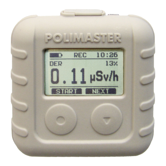
2.2 Operation 2.2.1 Switching the dosimeter ON To switch on the dosimeter press and hold any button until the LCD is activated. The dosimeter will go through the self-diagnostics and automatically enter the DER measurement mode (Figure 2.1). The dosimeter is ready for operation within 60 seconds after power on. 2.2.2 Controls The dosimeter is controlled by two multifunction buttons The LCD displays the dosimeter operation mode, its current status as well as functions of... -
Page 14: Switching The Dosimeter Off
2.2.4 Switching the dosimeter OFF To switch off the dosimeter, enter "SETTINGS", press "NEXT" to go to "POWER OFF" and press "SELECT", then press "YES" to confirm (Figure 2.4). Figure 2.4 2.2.5 DER measurement mode The dosimeter enters the DER measurement mode ("DER") automatically upon power on. In this mode the dosimeter can measure: - DER of continuous photon radiation;... -
Page 15: De Measurement Mode
When the dosimeter is moved to another place, re-start measurement of the average DER of pulsed radiation for more significant readings. Attention! The dosimeter writes the values of average DER of pulsed radiation into its operating history. The dosimeter monitors two settable alarm thresholds for the average DER of pulsed radiation. -
Page 16: Settings
If the time of warning alarm of the first dose equivalent threshold (ALARM1) is fixed, the do- simeter will produce three short signals every 10 minutes during this period until the alarm emits a signal informing that the first dose equivalent threshold is exceeded. If "TOTAL"... - Page 17 2.2.7.1 User-initiated writing of DER and DE history ("RECORD") To write the DER and DE history (date, time, event, value) manually, enter the "SETTINGS", select "RECORD" and press "YES". 2.2.7.2 Setting and viewing the data logging parameters ("HISTORY") "HISTORY" submenu: - "MEMORY"...
- Page 18 2.2.7.5 Setting alarm threshold levels for DER and DE, resetting DE ("THRESHOLD") Select "THRESHOLDS" to move to the settings of the alarm threshold levels for DER or DE . The LCD will display the following information, Figure 2.12. Figure 2.12 Select "DER"...
-
Page 19: Pc Communication Mode
To change the level of volume of sound alarm, select "SOUND", then press "NEXT". Press "-" to reduce the sound volume. The sound alarm can be switched off using "-" button. Press "+" to increase the volume. You can set maximum volume of the sound alarm using "+" button. To exit the sound volume settings, press "DONE". -
Page 20: Low Battery Indication And Lcd Backlight
To disconnect computer communication, press "BACK" – the dosimeter will go into the DER measurement mode. To connect computer communication, enter the "SETTINGS" and select "USB". When upon the connection of USB cable to the dosimeter the communication with computer isn’t established automatically go into “SETTINGS”, select line USB and shortly press “SELECT”. -
Page 21: Maintenance
3 Maintenance 3.1 Maintenance of the dosimeter involves preventive check, battery replacement and regular performance check according to 2.1.4. 3.2 Preventive check includes external examination, dusting and decontamination in the case of radioactive contamination. For decontamination wipe the case of the instrument using a cloth wetted with ethanol. -
Page 22: Verification Method
5 Verification method 5.1 Introduction 5.1.1 This verification procedure defines methods and tools of primary and periodic verifi- cation procedure of the X-Ray and Gamma Personal Dosimeters РМ1610, РМ1610А, РМ1610В, РМ1610-01, РМ1610А-01, РМ1610В-01 (further – instruments). 5.1.2 Produced instruments and instruments repaired because of non-compliance of metro- logical performance with specification requirements are subject to primary verification. - Page 23 Table 5.2 Verification procedure chapter num- Names of the reference ber at Main metrological and technical charac- and auxiliary verifica- teristics primary verifica- periodic verifica- tion tools tion tion Reference verification DER measurement range from 5.8.3.1, 5.8.3.1, assembly with 0.1 μSv/h to 10 Sv/h. 5.8.3.2 5.8.3.2 sources set, according to...
- Page 24 5.7 Pre-verification procedure 5.7.1 Verification procedure of the instruments РМ1610, РМ1610А, РМ1610-01 and РМ1610А-01 is carried out with fully charged accumulator batteries. Verification procedure of the instruments РМ1610B and РМ1610B-01 is carried out with new batteries with guaranteed expira- tion date. 5.7.2 The following pre-verification procedures are required: - study carefully Operation Manual before working with the Instruments to prevent errors and ensure safe operation.
- Page 25 Phantom Direction radiation flux Detector geometric center Figure 5.1 – The method of placing the dosimeter with phantom on the dosime- ter calibration assembly 4) create reference DER = 3.0 Sv/h in the point coinciding with the geometric center of the detector and irradiate the instrument; 5) in 600 s after the beginning of irradiation take five the dosimeter’s readings at intervals of not less than 60 s and calculate the average value...
-
Page 26: Disposal
where Q – uncertainty of the reference dosimeter assembly, %; – maximum measurement error of all Qj values, %; jmax 13) compare the calculated value with an acceptable value calculated by formula: - for РМ1610 and РМ1610-01 instruments ...
Need help?
Do you have a question about the PM1610B and is the answer not in the manual?
Questions and answers