
Related Manuals for KYORITSU 3131A


Summary of Contents for KYORITSU 3131A
- Page 1 INSTRUCTION MANUAL ANALOGUE INSULATION/CONTINUITY TESTER MODEL 3131A GlobalTestSupply www. .com Find Quality Products Online at: sales@GlobalTestSupply.com...
-
Page 2: Table Of Contents
Contents 1. Safety Warnings ..................1 2. Features ....................5 3. Specifications ..................6 4. Instrument Layout ................. 8 5. Preparation for Testing ................. 10 5-1 Removing the Cover ..............10 5-2 Mechanical Zero Adjustment ............11 5-3 Battery Voltage Check ..............11 5-4 Test Probe Connection .............. -
Page 3: Safety Warnings
It is essential that the above instructions are adhered to. Failure to follow the above instructions may cause injury, instrument damage and/or damage to equipment under test. Kyoritsu is by no means liable for any damage resulting from the instrument in contradiction to these cautionary notes. - Page 4 Please refer to following explanation of the symbols used on the instrument and in this manual. User must refer to the explanations in the instruction manual. Caution, risk of electric shock. Instrument with double or reinforced. Protection against wrong connection is up to 440V. ...
- Page 5 ● Do not install substitute parts or perform any unauthorized modification of the instrument. Return the instrument to Kyoritsu or your distributor for service and repair to ensure the safety features are maintained. ● Do not try to replace the batteries and fuse if the surface of the instrument is wet.
- Page 6 Measurement categories (Over-voltage categories) To ensure safe operation of measuring instruments, IEC 61010 establishes safety standards for various electrical environments, categorized as O to CAT IV, and called measurement categories. Higher-numbered categories correspond to electrical environments with greater momentary energy, so a measuring instrument designed for CAT III environments can endure greater momentary energy than one designed for CAT II.
-
Page 7: Features
2. Features MODEL-3131A is an analogue insulation tester with five ranges for insulation resistance measurement and continuity testing (resistance tests) of low voltage installations. ● Designed to safety standards: IEC61010-1 IEC61010-031 IEC 61557-1,2,4,10 ● Dust and drip proof constrution to IP54 ●... -
Page 8: Specifications
3. Specifications ● Measuring Range and Accuracy (at 23±5℃, relative humidity 45-75%) Insulation Resistance Ranges:(IEC 61557-2) Nominal Output Voltage 250V 500V 1000V Measuring Ranges 0 - 100MΩ 0 - 200MΩ 0 - 400MΩ Open-Circuit 250V DC +20% max. 500V DC +20% max. 1000V DC + 20% max. - Page 9 Typical Number of Measurements (central tendency for supply voltage up to 6.5V) Insulation Resistance Ranges: 1000V/400MΩ Range Approx. 500 times min. 500V/200MΩRange Approx. 1300 times min. 250V/100MΩ Range Approx. 1800 times min. Continuity Test (Resistance Test) Ranges: x1Ω Range/ x 10Ω Range Approx.
-
Page 10: Instrument Layout
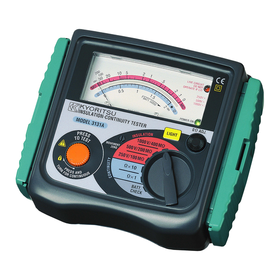
4. Instrument Layout Fig.1 Part names ①METER MOVEMENT ZERO ADJUST ②TEST BUTTON ③SCALE PLATE ④LIVE CIRCUIT WARNING LED ⑤POWER-ON INDICATION LED ⑥CONTINUITY ZERO ADJUST ⑦LIGHT SWITCH ⑧RANGE SELECTOR SWITCH ⑨TEST PROBE (RED) LINE PROBE ⑩TEST PROBE (BLACK) EARTH PROBE ⑪ALLIGATOR CLIP (BLACK) ⑫PROTECTIVE FIGERGUARD —... - Page 11 Protective fingerguard Protective fingerguard: It is a part providing protection against electrical shock and ensuring the minimum required air and creepage distances. Cap: Uncapped condition for CAT.II environment Capped condition for CAT.III/ IV environments The Cap shuld be firmly attached to the probes. —...
-
Page 12: Preparation For Testing
5. Preparation for Testing 5-1 Removing the Cover Model 3131A has a dedicated cover to protect against an impact from the outside and prevent the operation part, and the connector socket from becoming dirty. Remove the cover and put it on the back side of the main body to make measurements. -
Page 13: Mechanical Zero Adjustment
5-2 Mechanical Zero Adjustment Check that the pointer lines up with the middle of the mark on the scale correctly. If not, adjust it by rotating the meter movement zero adjust with a screwdriver, etc. 5-3 Battery Voltage Check ... -
Page 14: Operation
6. Operation 6-1 Disconnection and check of power source of circuit under test DANGER ● To avoid possible electrical shock, do not perform measurements on energized (LIVE) circuits. ● Never make measurements with the battery compartment cover removed. ● Always Keep your fingers and hands behind the protective fingerguard on test probe to avoid the possible shock hazard. -
Page 15: Insulation Resistance Measurement
6-2 Insulation Resistance Measurement DANGER ● Always test the circuit or equipment to ensure it is surely de-energized before measurement according to the instruction of 6-1. ● To avoid electrical shock, measurements must be performed on de- energized circuits only. ●... -
Page 16: Continuity Testing (Resistance Tests)
DANGER Do not touch the circuit under test immediately after testing. Capacitance stored in the circuit may cause electric shock. Leave the test probe connected to the circuit and never touch the circuit until the discharge is completed. Principle of Insulation Resistance Measurement ... -
Page 17: Continuous Measurement
① Set the range selector switch to the desired position x 1Ωor x 10Ω. ② Short the line probe (red) and the earth clip of the test probe (black) and press the test button. Adjust the ohm zero adjust to zero the pointer on the scale. -
Page 18: Back Light Function
7. Back Light Function To facilitate working at night or dimly lit situations, a back light function is provided which illuminates the display. To operate this function, the back light button must be pressed and released while pressing the test button. The back light continues illuminating for approx. -
Page 19: Battery & Fuse Replacement
8. Battery & Fuse Replacement DANGER ● Never open the battery compartment cover while making measurement. To avoid possible electrical shock, disconnect the test probe before opening the cover for battery and fuse replacement. ● Replacement fuse must have the following rating. Fast acting type, F500mA/600V, φ6.35×32mm 8-1 Battery Replacement ... -
Page 20: Notes On Accessories
9. Notes on Accessories 9-1 How to Fit Strap Belt and Test Probe Pouch By hanging the instrument around the neck, both hands can be used freely for easy and safety working. ① How to fit the strap belt Fig.9 How to fit the strap belt ... -
Page 21: Cleaning Of The Instrument
10. Cleaning of the Instrument ◎ Cleaning the meter cover This instrument is managed by our company's quality standard and is delivered in the best condition after passed the inspection. But in the dry time of winter static electricity sometimes builds up on the meter cover due to the characteristic of plastic.
Need help?
Do you have a question about the 3131A and is the answer not in the manual?
Questions and answers