Table of Contents
Advertisement
Quick Links
USER GUIDE
ATSAMD10 Xplained Mini User Guide
Introduction
®
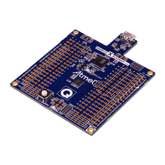
This user guide describes how to get started with the Atmel
ATSAMD10
Xplained Mini board.
The ATSAMD10 Xplained Mini evaluation kit is a hardware platform to evaluate
the Atmel ATSAMD10 microcontroller. The evaluation kit comes with a fully
integrated debugger that provides seamless integration with Atmel Studio 6.2
(and later version). The kit provides access to the features of the ATSAMD10
enabling easy integration of the device in a custom design.
42387A-MCU-01/2015
Advertisement
Table of Contents

Subscribe to Our Youtube Channel
Related Manuals for Atmel ATSAMD10 Xplained Mini


Summary of Contents for Atmel ATSAMD10 Xplained Mini
-
Page 1: Introduction
This user guide describes how to get started with the Atmel ATSAMD10 Xplained Mini board. The ATSAMD10 Xplained Mini evaluation kit is a hardware platform to evaluate the Atmel ATSAMD10 microcontroller. The evaluation kit comes with a fully integrated debugger that provides seamless integration with Atmel Studio 6.2 (and later version). -
Page 2: Table Of Contents
Connecting an Arduino Shield ........3 1.3.3. Standalone Node ............3 1.4. Connecting the Kit ..............3 1.4.1. Connect the Kit to Atmel Studio ........3 1.4.2. Connect the Target UART to the mEBDG COM Port ..3 1.5. Programming and Debugging ..........3 1.5.1. -
Page 3: Getting Started
1.3.3 Standalone Node The ATSAMD10 Xplained Mini board can be used as a standalone node - use the 4xAAA or 2xAAA battery pack available in Atmel store to provide power. Connecting the Kit How to connect the evaluation board. -
Page 4: Programming The Target Using Medbg
Using the Embedded Debugger on the Xplained Mini board to program the ATmega328 via the SPI bus. 1. Connect the mEDBG USB to the PC. 2. Go to Atmel Studio: click Tools, select Device Programming, and select the connected mEDBG as Tool with Device = ATSAMD10 and Interface = SWD, click Apply. -
Page 5: Programming The Atmega32U4 Using A Bootloader
4. Connect the board USB connector to the PC. 5. Select Device = ATmega32U4 (Device - Select). 6. Select USB communication (Ctrl+U). 7. Select memory area to program (Use the toggle memory button bellow the Atmel logo). 8. Select Load Hex file (Ctrl+L). 9. Select Programming Options. - Page 6 2. Run the FLIP Installer. ATSAMD10 Xplained Mini User Guide [USER GUIDE] 42387A-MCU-01/2015...
-
Page 7: Hardware User Guide
The board headers and connectors. 2.3.1 JTAG (J100) J100 is the JTAG programming header typically used by the JTAGICE for programming of the ATmega32U4 (mEDBG). Table 2-1. J100 JTAG Header J100 pin Signal function JTAG_TCK ATSAMD10 Xplained Mini User Guide [USER GUIDE] 42387A-MCU-01/2015... -
Page 8: Usb (J101)
SPI-SERCOM1 or PWM TCC0/WO[4] J200-5 PA24/SPI-MISO SPI-SERCOM1 or PWM TCC0/WO[2] J200-6 PA09/SCK Yellow USER LED D200 connected. - SPI-SERCOM1 J200-7 J200-8 PA03/AREF J200-9 PA14/SDA TWI Serial Data. SERCOM2 J200-10 PA15/SCL TWI Serial Clock. SERCOM2 ATSAMD10 Xplained Mini User Guide [USER GUIDE] 42387A-MCU-01/2015... -
Page 9: Target Analogue I/O (J203)
3.3V from on-board DC/DC converter (U300). VCC_P5V0 Voltage from the selected power source, default VBUS. VCC_VIN The externally connected power source if any. 2.3.6.1 Power Supply Configuration The J300 and J301 headers enables Power supply configuration. ATSAMD10 Xplained Mini User Guide [USER GUIDE] 42387A-MCU-01/2015... -
Page 10: Target Spi (J204)
The J204 header enable direct connection to ISP for programming of the ATSAMD10 or to use the SPI bus to connect external equipment. Table 2-10. J204 SPI Header J204 pin Function MISO (PA24) VCC target (ATSAMD10) SCK (PA09) MOSI (PA22) RESET ATSAMD10 Xplained Mini User Guide [USER GUIDE] 42387A-MCU-01/2015... -
Page 11: Extension Headers
Slave select for SPI and/or general purpose I/O. Wake up GPIO interrupt to RF extension (SLP_TR). TWI_SDA PC4/SDA M6 to Data line for two-wire interface. TWI_SCL PC5/SCL M9 to Clock line for two-wire interface. ATSAMD10 Xplained Mini User Guide [USER GUIDE] 42387A-MCU-01/2015... -
Page 12: Board Gui
A mechanical and a touch button is available for general use by application SW. Table 2-13. Buttons Button Function ATSAMD10 pin SW200 User defined high signal, press to ground PA25 (negate). QT200 Qtouch button PA07 ATSAMD10 Xplained Mini User Guide [USER GUIDE] 42387A-MCU-01/2015... -
Page 13: Factory Programmed Data
When the CDC COM port is connected to a terminal window (9600/N81), the text you write will be transmitted via the LED in Morse code. Any Morse code transmitted by using the switch will be displayed as text in the terminal window. ATSAMD10 Xplained Mini User Guide [USER GUIDE] 42387A-MCU-01/2015... -
Page 14: Document Revision History
Document Revision History Document Date Comment revision 42387A 02/2015 Initial document release ATSAMD10 Xplained Mini User Guide [USER GUIDE] 42387A-MCU-01/2015... - Page 15 OR LOSS OF INFORMATION) ARISING OUT OF THE USE OR INABILITY TO USE THIS DOCUMENT, EVEN IF ATMEL HAS BEEN ADVISED OF THE POSSIBILITY OF SUCH DAMAGES. Atmel makes no representations or warranties with respect to the accuracy or completeness of the contents of this document and reserves the right to make changes to specifications and products descriptions at any time without notice.
- Page 16 Mouser Electronics Authorized Distributor Click to View Pricing, Inventory, Delivery & Lifecycle Information: Atmel ATSAMD10-XMINI...
- Page 17 Компания «ЭлектроПласт» предлагает заключение долгосрочных отношений при поставках импортных электронных компонентов на взаимовыгодных условиях! Наши преимущества: Оперативные поставки широкого спектра электронных компонентов отечественного и импортного производства напрямую от производителей и с крупнейших мировых складов; Поставка более 17-ти миллионов наименований электронных компонентов; ...
Need help?
Do you have a question about the ATSAMD10 Xplained Mini and is the answer not in the manual?
Questions and answers