Table of Contents
Advertisement
Quick Links
Atmel ATA6612/ATA6613/ATA6614-EK Development
Features
●
All necessary components to put the Atmel
operation are included
●
Placeholders for some optional components for extended functions included
●
All pins easily accessible
●
Easily adaptable watchdog times by replacing a single resistor
●
Possibility to activate an external NPN-transistor for boosting up the output current
of the voltage regulator (jumper JP3)
●
Possibility of selecting between master or slave operation (mounting D2 and R1)
●
Possibility to mount an external quartz to handle time-critical applications (not
necessary for LIN communication)
●
Push button included for creating a local wake-up after having entered the sleep or
silent mode
●
Ground coulter clip for connecting probes easily when measuring with the
oscilloscope
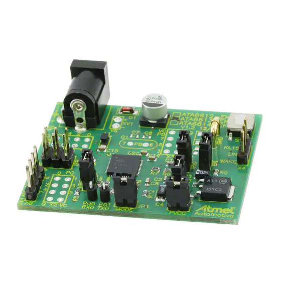
Figure 1.
Atmel ATA6612/ATA6613/ATA6614 Development Board
APPLICATION NOTE
Board V1.2
ATA6612/ATA6613/ATA6614
®
ATA6612/ATA6613/ATA6614 in
9127E-AUTO-03/15
Advertisement
Table of Contents

Related Manuals for Atmel ATA6612-EK


Summary of Contents for Atmel ATA6612-EK
- Page 1 APPLICATION NOTE Atmel ATA6612/ATA6613/ATA6614-EK Development Board V1.2 ATA6612/ATA6613/ATA6614 Features ® ● All necessary components to put the Atmel ATA6612/ATA6613/ATA6614 in operation are included ● Placeholders for some optional components for extended functions included ● All pins easily accessible ● Easily adaptable watchdog times by replacing a single resistor ●...
- Page 2 Standby mode: the crystal/resonator oscillator is running while the rest of the device is sleeping. This allows very fast start-up combined with low power consumption. The Atmel ATA6624, included in the Atmel ATA6612 and the Atmel ATA6613, as well as the Atmel ATA6630 included in the Atmel ATA6614, provide the following features: ●...
- Page 3 LIN communication. Please note that the Atmel ATA6630 inside the Atmel ATA6614 signals the wake up source in a different way as the Atmel ATA6624 inside the Atmel ATA6612 and the Atmel ATA6613. Additionally the Atmel ATA6630 also signals a V...
-
Page 4: Quick Start
® The development board for the Atmel ATA6612, Atmel ATA6613 and the Atmel ATA6614 is shipped with the default jumper settings and all accessories required for immediate use. The IC mounted on the board is pre-programmed with a firmware in order to test and to understand the basic functions directly on the board. - Page 5 Figure 2-1. Atmel ATA6612/ATA6613/ATA6614-EK Board Overview The board's pre-programmed firmware provides the window watchdog with a valid trigger signal so that the NRES pin is not forced to Ground and the microcontroller does not receive any resets. For testing purposes and for understanding the system, it can be helpful to see the behavior when the watchdog is not triggered correctly.
-
Page 6: Hardware Description
Voltage Regulator (PVCC and VCC) ® The internal 5V voltage regulator is capable of driving loads with up to 85mA current consumption. Therefore, the Atmel ATA6612, the Atmel ATA6613 and the Atmel ATA6614 are able to supply the internal microcontroller, some external sensors, and/or other ICs required for the particular LIN node. - Page 7 In general, the Atmel ATA6612, ATA6613 and ATA6614 are shipped with an oscillator start-up time of 65ms. Due to the extra-long lead time of 155ms it should be possible in almost all cases to meet the first open window of the watchdog. If more time is needed, the default start-up time of the microcontroller 65ms can be reduced via the fuse bits to 4.1ms or even 0ms.
- Page 8 As the ADC6 as well as the ADC7 can only be used for converting analog signals to digital values, and there is no analog ® output from the Atmel ATA6612, the Atmel ATA6613 and the Atmel ATA6614 to measure, these two input pins have been led off the board in order to be externally connected if required. 3.1.7 WAKE (LIN SBC) The high-voltage input pin WAKE can be used to generate a low-active local wake-up from sleep mode or silent mode.
-
Page 9: Port Connectors
Port Connectors The Atmel ATA6612/ATA6613/ATA6614-EK has three port connectors for the microcontroller ports PortB, PortC and PortD. All non-reserved I/O pins available from the microcontroller are routed to the corresponding connectors to give the user easy access to them. -
Page 10: Jumper Description
Figure 3-2. Pinout of the Port Connectors Jumper Description In order to be more flexible and to meet as many requirements as possible, some jumpers are provided on the development board. With the help of these jumpers, users have the opportunity to engage with the system itself in order to test some features and/or to adapt the system to their requirements. -
Page 11: Optional Components
The difference regarding the hardware between a master node and a slave node is the additional diode D together ser_master with a serial 1k resistor between V and the LIN line. The placeholders for these two components D2 and R1 on the Atmel ATA6612/ATA6613/ATA6614 [APPLICATION NOTE] 9127E–AUTO–03/15... - Page 12 For cases in which the accuracy of the internal RC-oscillator is not sufficient to meet the application-specific requirements, ® an external crystal oscillator plus the two capacitors can be mounted on the Atmel ATA6612/ATA6613/ATA6614-EK. The location of these placeholders is shown in Figure 3-5.
- Page 13 Figure 3-6. Location of Resistor R8 A description of how the resistor R8 influences the watchdog timing can be found in Section 3.1.3 “The Window Watchdog (NTRIG, WD_OSC and NRES)” on page 6 and in the Atmel ATA6612/ATA6613/ATA6614 datasheet. ATA6612/ATA6613/ATA6614 [APPLICATION NOTE] 9127E–AUTO–03/15...
- Page 14 Atmel ATA6612/ATA6613/ATA6614-EK via the 6-wire cable. Pin “1” is marked with two little triangles on the board. In the Atmel Studio, the three devices Atmel ATA6612, Atmel ATA6613 and the Atmel ATA6614 are not listed in the supported devices list, as they contain the standard devices Atmel ATmega88, Atmel ATmega168 and the Atmel ATmega328P respectively.
- Page 15 Many OEMs demand that their suppliers use certified LIN protocol stacks from a third party. To meet this requirement there are LIN2.0 as well as LIN2.1 protocol stacks available for the Atmel ATA6612 (Atmel Atmega88) as well as for the Atmel ®...
- Page 16 Appendix Schematic and Layout of the Development Board for the Atmel ATA6612/ATA6613/ATA6614 Figure 7-1. Schematic of the Development Board for the Atmel ATA6612/ATA6613/ATA6614 GND1 GND2 LL4148 PD1_TXD PD0_RXD DC-Socket ADC6 NTRIG AREF ADC7 22pF 22pF TRIG Quarz KL_15 WAKE ENABLE 100nF 10µH...
- Page 17 Figure 7-2. Atmel ATA6612/ATA6613/ATA6614 Board Component Placement; Top Side, Top View Figure 7-3. Atmel ATA6612/ATA6613/ATA6614 Development Board; Top Side, Top View ATA6612/ATA6613/ATA6614 [APPLICATION NOTE] 9127E–AUTO–03/15...
-
Page 18: Further Information
Figure 7-4. Atmel ATA6612/ATA6613/ATA6614 Development Board; Bottom Side, Top View Further Information 7.2.1 Datasheets ® Atmel ATA6612/ATA6613 complete version http://www.atmel.com/Images/Atmel-9111-LIN-Networking-ATA6612C-ATA6613C_Datasheet.pdf Atmel ATA6624 complete version http://www.atmel.com/Images/Atmel-4986-LIN-Networking-ATA6622-ATA6624-ATA6626_Datasheet.pdf Atmel ATmega48/88/168 Automotive http://www.atmel.com/Images/doc7530.pdf Atmel ATmega88 Automotive - 150°C Specification - Appendix A Preliminary http://www.atmel.com/dyn/resources/prod_documents/doc7607.pdf Atmel ATA6614 complete version http://www.atmel.com/Images/Atmel-9240-LIN-Networking-ATA6614Q_Datasheet.pdf... -
Page 19: Revision History
AVR322: LIN Protocol Implementation on Atmel AVR Microcontrollers http://www.atmel.com/dyn/resources/prod_documents/doc7548.pdf The LIN protocol is introduced in this application note, along with its implementation on Atmel Automotive AVR microcontrollers. Revision History Please note that the following page numbers referred to in this section refer to the specific revision mentioned, not to this document. - Page 20 DISCLAIMER: The information in this document is provided in connection with Atmel products. No license, express or implied, by estoppel or otherwise, to any intellectual property right is granted by this document or in connection with the sale of Atmel products. EXCEPT AS SET FORTH IN THE ATMEL TERMS AND CONDITIONS OF SALES LOCATED ON THE ATMEL WEBSITE, ATMEL ASSUMES NO LIABILITY WHATSOEVER AND DISCLAIMS ANY EXPRESS, IMPLIED OR STATUTORY WARRANTY RELATING TO ITS PRODUCTS INCLUDING, BUT NOT LIMITED TO, THE IMPLIED WARRANTY OF MERCHANTABILITY, FITNESS FOR A PARTICULAR PURPOSE, OR NON-INFRINGEMENT.
Need help?
Do you have a question about the ATA6612-EK and is the answer not in the manual?
Questions and answers