Table of Contents
Advertisement
Quick Links
I N S T R U C T I O N M A N U A L
To w e r
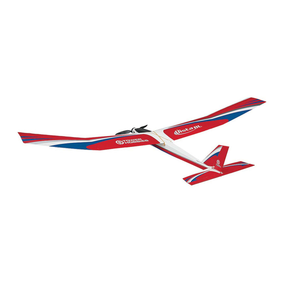
WINGSPAN
WING LOADING
LENGTH
®
Hobbies
78.5 in [1995mm]
41 in [1040 mm]
7.5 – 8.0 oz/ft
2
[23 – 24 g/dm
2
]
guarantees
this kit to be
free from defects
MOTOR
WING AREA
RADIO
in both material and
Included
678 sq in [43.7 dm
2
]
3-Channel, Two Standard Servos
workmanship
at
the
date of purchase. This
or Two Mini Servos with
warranty does not cover any
WEIGHT
at least 35 g of torque.
component parts damaged by
use or modification. In no case
35 – 38 oz [992 –1077g]
shall Tower Hobbies' liability exceed
the original cost of the purchased kit.
Further, Tower Hobbies reserves the right to
change or modify this warranty without notice.
READ THROUGH THIS MANUAL
In that Tower Hobbies has no control over the final
assembly or material used for final assembly, no
BEFORE STARTING CONSTRUCTION.
liability shall be assumed nor accepted for any damage
IT CONTAINS IMPORTANT INSTRUCTIONS
resulting from the use by the user of the final
user-assembled
product.
By
the
act
of
using
the
AND WARNINGS CONCERNING THE
user-assembled product, the user accepts all resulting liability.
ASSEMBLY AND USE OF THIS MODEL.
If the buyer is not prepared to accept the liability associated with the
use of this product, the buyer is advised to return this kit immediately in
new and unused condition to the place of purchase.
TOWER HOBBIES
To make a warranty claim send the defective part or item to Hobby Services at
the address below:
Champaign, Illinois
Hobby Services • 3002 N. Apollo Dr. Suite 1 • Champaign IL 61822 • USA
(217) 398-8970 ext. 5
Include a letter stating your name, return shipping address, as much contact information
as possible (daytime telephone number, fax number, e-mail address), a detailed description
airsupport@hobbico.com
of the problem and a photocopy of the purchase receipt. Upon receipt of the package the
problem will be evaluated as quickly as possible.
®
© 2014 Tower Hobbies.
A subsidiary of Hobbico, Inc.
TOWA4020
Advertisement
Table of Contents

Subscribe to Our Youtube Channel
Related Manuals for Tower Hobbies VistaBL


Summary of Contents for Tower Hobbies VistaBL
-
Page 1: Tower Hobbies
Further, Tower Hobbies reserves the right to change or modify this warranty without notice. READ THROUGH THIS MANUAL In that Tower Hobbies has no control over the final assembly or material used for final assembly, no BEFORE STARTING CONSTRUCTION. liability shall be assumed nor accepted for any damage... -
Page 2: Table Of Contents
INTRODUCTION –––––––––––––––––––––––– 4. You must use an R/C radio system that is in fi rst-class condition. Thank you for purchasing the TOWER HOBBIES Vista ™ EP ARF motor glider. Identical in construction to the Vista 5. You must correctly install all R/C and other components so ARF sailpane, this BL version features a 35mm brushless motor that the model operates correctly on the ground and in the air. -
Page 3: Additional Items Required
■ ElectriFly 2200mAh 30C (GPMP0861) ORDERING REPLACEMENT PARTS –––– ■ FlightPower 2200mAh 30C (FPWP3223) Replacement parts for the Tower Hobbies Vista BL EP ARF are ■ FlightPower 2200mAh 50C (FPWP5223) available using the order numbers in the Replacement Parts List that follows. The fastest, most economical service can be Most modelers may already have a suitable LiPo charger, but provided by your hobby dealer or mail-order company. -
Page 4: Contents
Mail parts orders Hobby Services REPLACEMENT PARTS LIST and payments by 3002 N Apollo Drive, Suite 1 personal check to: Champaign IL 61822 Order No. Description Be certain to specify the order number exactly as listed in the T O WA 4 0 2 1 Fuselage Replacement Parts List. -
Page 5: Assembly
ASSEMBLY ––––––––––––––––––––––––––––– Preparations ❏ 2. Place a sheet of wax paper on your workbench and gather all the items required for joining the wings: 30-minute epoxy, a mixing cup, an epoxy mixing stick, an epoxy brush, paper towels and denatured alcohol for epoxy clean up. Hint: To cut down on waste, cut the paper towels into several small squares ❏... -
Page 6: Assemble The Fuselage
❏ 2. Place the stab on the fuselage, keying the notches in the ❏ 4. Coat the protruding end of the joiner all the way around stab into the pegs on the fuselage. Use a fi ne-point, felt-tip pen with epoxy and pour epoxy into the other wing. Join the wing to to mark the outline of the fuselage onto the stab. -
Page 7: Join The Fin
❏ 5. Reposition the stabilizer onto the fuselage. Resting the fuselage on your workbench, place a weight on top of the stab to hold it down. View the fuselage from the rear. If the stab is parallel with the workbench, proceed to the next step. If the stab is not parallel with the workbench, remove the stab and use medium-grit sandpaper to sand down the “high side”... -
Page 8: Hook Up The Controls
Hook Up the Controls ❏ 1. Connect the clevis to the third hole out from the bottom of the elevator horn. ❏ 5. Take out the T-pins. Glue the tri-stock fi n braces into position with 30-minute epoxy, using T-pins to hold them in place. Note: If the silicone retainer on the elevator clevis rubs against the inside of the fuselage sides, use a hobby knife to trim the inside of the fuselage as necessary for free, smooth movement. - Page 9 Refer to this photo for the following four steps. ❏ 8. Use pliers to make a 90° bend in the pushrod at the mark you made. ❏ 3. Position the servos on the rails and slide them forward against the forward rail. Note the position of the splined output 1/16”...
-
Page 10: Mount The Receiver
GET THE MODEL READY TO FLY –––––– Mount the Receiver Check the ESC ATTENTION!!! Great care must always be used when working on electric-powered models. Unlike glow engines, electric motors can turn on unexpectedly if you aren’t paying attention and inadvertently activate the throttle. Follow these instructions to operate the motor correctly and be certain it is properly set up. -
Page 11: Check The Control Directions
Set the Control Throws ATTENTION!!! The motor battery should never be plugged in without the transmitter switch being on. Otherwise, the receiver could pick up errant signals, inadvertently causing the servos to move or the motor to activate. Always turn on the transmitter fi... -
Page 12: Apply The Decals
❏ 2. Install the propeller and propeller backplate on the prop adapter. Make sure the hex on the prop adapter keys into the hex on the back of the backplate. Secure the prop to the adapter with the plastic washer and aluminum hex nut, making sure to leave a 1/16"... -
Page 13: Preflight
❏ 4. After determining the amount of weight required, remove the model from the CG Machine and adhere the weight where needed–to the side of the fuselage under the tail or inside the fuselage behind the motor. ❏ 5. IMPORTANT: If you found it necessary to add any weight, recheck the C.G. -
Page 14: Motor Safety Precautions
MOTOR SAFETY PRECAUTIONS –––––––– 5) I will not fl y my model unless it is identifi ed with my name and address or AMA number, on or in the model. Note: This does not apply to models while being fl own indoors. Failure to follow these safety precautions may result in severe injury to yourself and others. -
Page 15: Find A Safe Place To Fly
FIND A SAFE PLACE TO FLY ––––––––––– Takeoff IMPORTANT: If you are an inexperienced modeler we strongly The best place to fl y any model is at an AMA chartered club urge you to seek the assistance of a competent, experienced R/C fi... -
Page 16: Flight
separate timer with an alarm to alert you when the battery may Downwind Leg be getting low. This will require a few fl ights before determining the maximum fl ight time you can achieve with the batteries. This will prevent the downwind auto motor cutoff over the end of the fl...
Need help?
Do you have a question about the VistaBL and is the answer not in the manual?
Questions and answers