Table of Contents
Advertisement
Quick Links
2009-2014 Yamaha YFZ450 R/X
2009-2014 Yamaha YFZ450 R/X
I n s t a l l a t i o n I n s t r u c t i o n s
PLEASE READ ALL DIRECTIONS BEFORE STARTING INSTALLATION
IFC22007.01
www.powercommander.com
2191 Mendenhall Drive North Las Vegas, NV 89081 (800) 992-4993 www.powercommander.com
Parts List
Parts List
1
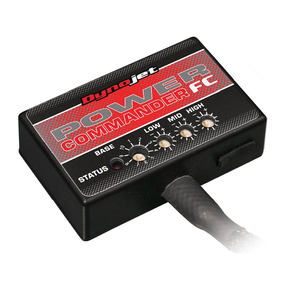
Power Commander FC
1
USB Cable
1
Installation Guide
2
Dynojet Decals
2
Velcro
1
Alcohol swab
THE IGNITION MUST BE TURNED
OFF BEFORE INSTALLATION!
YOU CAN ALSO DOWNLOAD THE PCFC
CONTROL CENTER SOFTWARE AND
LATEST MAPS FROM OUR WEB SITE AT:
www.powercommander.com
2009-2014 Yamaha YFZ450 R/X - 1
Advertisement
Table of Contents

Related Manuals for Dynojet Power Commander FC


Summary of Contents for Dynojet Power Commander FC
- Page 1 Parts List Parts List Power Commander FC USB Cable 2009-2014 Yamaha YFZ450 R/X 2009-2014 Yamaha YFZ450 R/X Installation Guide Dynojet Decals I n s t a l l a t i o n I n s t r u c t i o n s...
- Page 2 SELECTING THE MAP POSITION The Dynojet Power Commander Fuel Controller (PCFC) comes loaded with up to ten maps. Using a #1 Phillips screwdriver, turn the map select dial to toggle between the loaded maps. Refer to the map position table for the maps included in your PCFC.
- Page 3 FIG.A Remove the seat. Remove the side covers as shown in Figure A. Remove the fuel tank. FIG.B Temporarily lay the PCFC in the tail of the quad. Route the PCFC harness from the rear of the quad to the throttle body going along the left hand side of the frame.
- Page 4 FIG.D Route the 3-pin connectors from the PCFC harness down the left side of the throttle body as shown in Figure D. FIG.E Attach the PCFC wiring harness to the fuel injector and the stock wiring harness as shown in Figure E. FIG.F Unplug the throttle position sensor (TPS) connector from the left hand side of the throttle body as shown in Figure F.
- Page 5 FIG.G Attach the PCFC wiring harness to the stock TPS and wiring harness as shown in Figure G. FIG.H Attach the ground wire from the PCFC to the negative side of the battery as shown in Figure H. FIG.I Using the supplied velcro, secure the PCFC in the pocket of the rear fender on the left side as shown in Figure I.
Need help?
Do you have a question about the Power Commander FC and is the answer not in the manual?
Questions and answers