
Related Manuals for Avdel 07281


Summary of Contents for Avdel 07281
- Page 1 I n s t r u c t i o n M a n u a l Pass onto user to read and keep for reference Request Info 1-800-453-1692 www.aboveboardelectronics.com Jo-Bolt & Jo-Lok Power T ool 07281...
- Page 2 AVDEL policy is one of continuous development. Specifications shown in this document may be subject to changes which may be introduced after publication. For the latest information always consult Avdel. S P E C I F I C A T I O N S F O R 0 7 2 8 1 T O O L ■...
- Page 3 O N T E N T S S A F E T Y General Specific to 07281 Tool I N T E N T O F U S E General Tool Dimensions / Selection 4 - 5 P U T T I N G I N T O S E R V I C E...
- Page 4 RECOMMENDED AND SUPPLIED BY AVDEL. ANY MODIFICATION UNDERTAKEN BY THE CUSTOMER TO THE TOOL/MACHINE, NOSE ASSEMBLIES, ACCESSORIES OR ANY EQUIPMENT SUPPLIED BY AVDEL OR THEIR REPRESENTATIVES, SHALL BE THE CUSTOMER'S ENTIRE RESPONSIBILITY. AVDEL WILL BE PLEASED TO ADVISE UPON ANY PROPOSED MODIFICATION.
- Page 5 In addition to the general safety rules opposite, the following specific safety points must also be observed: THE OPERATING PRESSURE SHALL NOT EXCEED 8 BAR - 120 LBF/IN DO NOT OPERATE THE TOOL WITHOUT FULL NOSE EQUIPMENT IN PLACE. WHEN USING THE TOOL, THE WEARING OF SAFETY GLASSES IS REQUIRED BOTH BY THE OPERATOR AND OTHERS IN THE VICINITY TO PROTECT AGAINST FASTENER PROJECTION, SHOULD A FASTENER BE PLACED ‘IN AIR’.
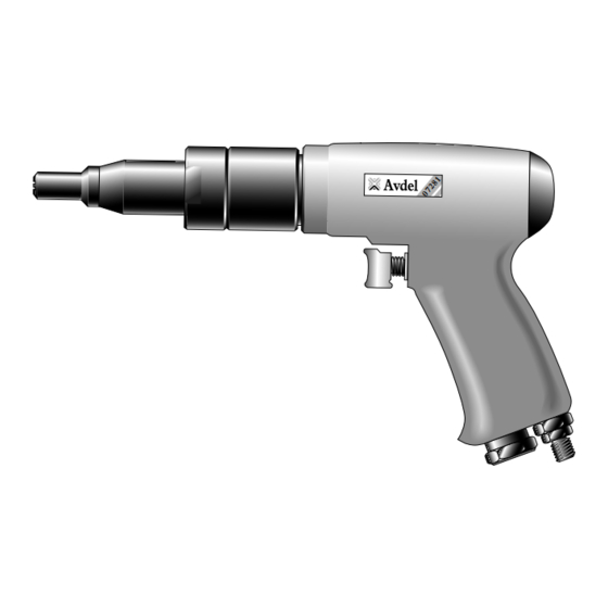
- Page 6 N T E N T O F U S E The pneumatic 07281 type tool is designed to place Avdel Jo-Bolt and Jo-Lock fasteners at high speed making it ideal for batch or flow- line assembly in a wide variety of applications throughout all industries.
- Page 7 A (i n ) B (i n ) C (i n ) NOSE ASSY PART N ¼ HEXAGON HEAD .164 12.45 22.94 31.52 1.24 07280-07000 07281-00005 (Alloy Steel & .190 12.45 22.35 30.94 1.22 07280-07100 07281-00006 Stainless Steel) .200 12.45 22.35...
- Page 8 All tools are operated with compressed air at an optimum pressure of 5.5 bar. We recommend the use of pressure regulators and automatic oiling/filtering systems on the main air supply. These should be fitted within 3 metres of the tool (see diagram below) to ensure maximum tool life and minimum tool maintenance.
- Page 9 Two different accessories are available to make the connection to your air supply: Hose Assembly Hose Connector part nº 07008-000324 part nº 07005-00276 TO FIT 6.4 mm (1/4”) BORE PIPE L = 137 cm 1/4” BSP Request Info 1-800-453-1692 www.aboveboardelectronics.com...
- Page 10 Nose assemblies are designed to place a specific size and type of head for either Jo-Bolt or Jo-Lok fasteners. If you have purchased a complete tool, it will already be fitted with the correct nose assembly for your fastener. It is essential that the correct nose assembly is fitted prior to operating the tool. By knowing your original complete tool part number or the details of the fastener to be placed, you can select a new complete nose assembly using the selection table on page 5.
-
Page 11: Servicing Instructions
SERVICING INSTRUCTIONS Nose assemblies should be serviced at weekly intervals. ■ Remove the complete nose assembly using the reverse procedure to the ‘Fitting Instructions’. ■ Any worn or damaged part should be replaced. ■ Particularly check wear on nose adaptor. ■... - Page 12 Regular servicing should be carried out and a comprehensive inspection performed annually or every 200000 cycles, whichever is soonest. I M P O R T A N T The employer is responsible for ensuring that tool maintenance instructions are given to the appropriate personnel. The operator should not be involved in maintenance or repair of the tool unless properly trained.
- Page 13 Every 200000 cycles the tool should be completely dismantled and components replaced where worn, damaged or when recommended. All ‘O’ rings and seals should be replaced with new ones and lubricated with Moly Lithium grease EP 3753 before assembling. I M P O R T A N T Safety Instructions appear on pages 2 &...
- Page 14 ■ Grip the tool pistol grip handle in a vice fitted with soft jaws. ■ Unscrew nose assembly from housing 1. ■ Using a spanner on the flats of ring gear 10, remove front gear assembly 3 and by the use of the flats of housing 1, unscrew rear gear assembly 13. ■...
- Page 15 ■ Remove locating pin 35 from side of front end plate 25. ■ Hold front end plate 25 and tap splined end of rotor 28 with a soft hammer so as not to damage the splines and remove front end plate 25 and bearing 26.
- Page 17 Request Info 1-800-453-1692 www.aboveboardelectronics.com...
- Page 18 ➝ Incorrect bore of hose ➝ Ensure bore of hose is 6.4 mm minimum Tool runs slowly ➝ Insufficient air volume ➝ Ensure there is no restriction in the air supply or connections ➝ Tool not properly lubricated internally ➝ Lubricate as per instructions ➝...
- Page 19 Engineered Fastening and Assembly Systems Declaration of Conformity Avdel UK Limited, Mundells, Welwyn Garden City, Herts, AL7 1EZ declare under our sole responsibility that the product type 07281 Serial Nº ..........to which this declaration relates is in conformity with the following standards or other formative documents...
- Page 20 Tel: +82 31 798 6340 Email: info@acument.com.au Email: AvdelDeutschland@acument.com Fax: +82 31 798 6342 Email: info@acumentkorea.com CANADA ITALY Avdel Canada, a Division of Acument Avdel Italia S.r.l. SPAIN Canada Limited Viale Lombardia 51/53 Avdel Spain S.A. 87 Disco Road 20047 Brugherio (MI)
Need help?
Do you have a question about the 07281 and is the answer not in the manual?
Questions and answers