Table of Contents
Advertisement
Available languages
Available languages
Quick Links
Betriebsanleitung
Üb e r s e t z u n g d e r O r i g i n a l - B e t r i e b s a n l e i t u n g
07535 MkII
07530
Druckluftgerät
Düko Vertriebs-GmbH
Lülsdorfer Straße 32
53842 Troisdorf
Telefon: 02241/2520150
Fax: 02241/25201511
E-Mail: info@dueko.com
Internet: www.dueko.com
Hr.-Nr.: 16390
Ust.-IdNr.: DE 122652573
Geschäftsführer: O. Düren
F. Düren
Advertisement
Chapters
Table of Contents

Subscribe to Our Youtube Channel
Related Manuals for Avdel 07535 MkII


Summary of Contents for Avdel 07535 MkII
- Page 1 Üb e r s e t z u n g d e r O r i g i n a l - B e t r i e b s a n l e i t u n g 07535 MkII 07530 Druckluftgerät...
-
Page 3: Table Of Contents
Garantiezeit geöffnet wurde. Bei Defekten oder Störungen repariert oder ersetzt Avdel nur fehlerhafte Komponenten nach eigenem Ermessen. Im Rahmen der Geschäftspolitik der ständigen Produktentwicklung und -verbesserung behält sich Avdel das Recht vor, Spezifikationen ohne vorherige Ankündigung zu ändern. -
Page 4: Sicherheitsvorschriften
übermäßiger Verschleiß auftritt sowie stets vor Erreichen der höchstzulässigen Anzahl von Nietungen. Wenden Sie sich bitte an Ihren Avdel Vertreter, der Ihnen den Wert mitteilt, nachdem er die Setzkraft Ihrer Anwendung mit einem kalibrierten Prüfgerät gemessen hat. Diese Prüfgeräte können auch unter der Artikelnummer 07900-... -
Page 5: Technische Daten
Technische Daten T E C H N I S C H E D A T E N F Ü R G E R Ä T T Y P 7 5 3 5 M K I I Betriebsdruck min./max. 5 - 7 bar (70 - 100 lbf/in Luftverbrauch bei 5,1 bar / 75 lbf/in 2,6 l (9,09 ft... -
Page 6: Arbeitsbereich
A R B E I T S B E R E I C H ® ® Das Druckluftgerät 07535 MkII wurde für das Setzen von Avdel Schnellsetznieten (ausgenommen 1/16” Avlug ) konstruiert. Es eignet sich deshalb ideal für die Serien- und Fließmontage mit den verschiedensten Einsatzzwecken in allen Industriezweigen. -
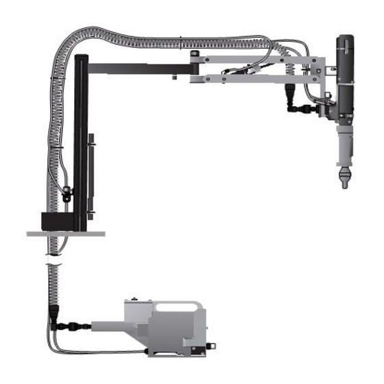
Page 7: Geräteabmessungen
Arbeitsbereich G E R Ä T E A B M E S S U N G E N - M O D E L L 0 7 5 3 5 M K I I 887.00 (34.921) Artikelnummer 07535-00011 415.00 (16.339) 100.00 (3.937) 175.00 (6.890) R295.00 (11.614) -
Page 8: Inbetriebnahme
Inbetriebnahme D R U C K L U F T V E R S O R G U N G Der Betrieb aller Geräte erfolgt durch Druckluft mit einem optimalen Druck von 5,5 bar. Wir empfehlen den Einsatz von Druckreglern und automatischen Öl-/Filtersystemen für die Hauptdruckluftversorgung. -
Page 9: Rücklaufsperre
Inbetriebnahme R Ü C K L A U F S P E R R E WICHTIG Bei falschem Einbau macht die Rücklaufsperre die Zuführung der Niete unmöglich. Obgleich die Rücklaufsperre bei Lieferung des Gerätes richtig herum eingebaut wurde, empfehlen wir vor Anbau der Ausrüstung deren Orientierung zu prüfen. -
Page 10: Arbeitsvorgang
Inbetriebnahme Laden des Gerätes • Die Druckluftversorgung am Gerät anschließen. • Die Spannbacken 9 zum Spannen des Dorns öffnen. Zu diesem Zweck das Schaltventil abschalten (Pos. 26, 29 und 30). • Das gewählte Mundstück auf den Lauf 25 des Gerätes aufschrauben. Einen Nietdorn durch das Papiermagazin gegen das hintere Ende der Niete einsetzen. -
Page 11: Kennzeichnung Und Lage Der Nietdornfedern
Inbetriebnahme KENNZEICHNUNG UND LAGE DER NIETDORNFEDERN BEZEICHNUNG NIETDORN-/NIETDORNFEDERN- MUNDSTÜCK NIETDORN- UND NIETBAUGRUPPE GRÖSSE NIET GRÖSSE (SIEHE ABSCHNITT ÜBER AUSRÜSTUNG) NIETDORNFEDER ANSCHLUSS NIETDORNKOPF NIETDORN 2,4mm STANDARD ALLE FEDER ABGESETZT & ABGESETZT 2,4mm BRIV ® ALLE MIT DREHÖFFNER 3,2mm ALLE ALLE 4,0mm ALLE ALLE 4,8mm... -
Page 12: Ausrüstungen
Ausrüstungen Auf Schnellnietgeräten wie Modell 07535 Mk II besteht die Ausrüstung stets aus drei Bauteilen: einem Mundstück, einem Nietdorn und einer Nietdornfeder. Diese drei Teile müssen zum gesetzten Niet und zum Lochdurchmesser passen. W I C H T I G Um ein vollständiges Zerlegen des Gerätes zu vermeiden, ist es notwendig, die Orientierung der Rücklaufsperre vor Einbau der Ausrüstung zu prüfen (siehe Abschnitt "RÜCKLAUFSPERRE"... - Page 13 Ausrüstungen A N S W A H L E I N E S M U N D S T Ü C K S • Bezeichnung, Größe und Werkstoff des zu setzenden Niets auflisten. • Den Niet in der ersten Spalte der Mundstück-Auswahltabellen aussuchen (auf STANDARD Seite 90 bei Verwendung von Zollmaßen und auf Seite 91 bei Verwendung von metrischen Einheiten).
- Page 14 Ausrüstungen A U S W A H L D E S M U N D S T Ü C K S - Z O L L M A S S Die Spalte "BEZ.-NR." verweist auf die Spalte "BEZ.-NR." im Abschnitt über Nietdorne. Sie kennzeichnet den für ein besonderes Mundstück mit einem spezifischen Niet erforderlichen Nietdorn sowie die Nietdornfeder.
- Page 15 Ausrüstungen A U S W A H L D E S M U N D S T Ü C K S - M E T R I S C H E M A S S E MUNDSTÜCK MUNDSTÜCK BEZ. BEZ. BLINDNIET MASSE MASSE...
-
Page 16: Nietdorne And Nietdornfedern
übermäßiger Verschleiß auftritt sowie stets vor Erreichen der höchstzulässigen Anzahl von Nietungen. Setzen Sie sich bitte mit Ihrem Avdel-Vertreter in Verbindung, der Ihnen den Wert bekanntgeben wird, nachdem er die Setzkraft Ihrer Anwendung mit unserem Prüfgerät zur Setzkraftmessung gemessen hat. Dieses Gerät kann auch unter der Teilnummer 07900-09080 mit allen für das Prüfen erforderlichen Informationen angekauft werden. - Page 17 Ausrüstungen Die unten links und rechts sowie auf den nächsten vier Seiten abgedruckten Tabellen enthalten eine Auflistung der Teilnummern für alle Nietdorne und Nietdornfedern pro Niet oder Nietengruppe, z.B. für Chobert ® und Grovit ® auf diesen Seiten. Während die Nietgrößen stets in den ihnen zugeordneten Maßeinheiten erscheinen, wurde jede Tabelle zweimal abgedruckt. Auf der linken Seite sind Zollmaße und auf der rechten Seite metrische Maße angegeben.
- Page 18 Ausrüstungen Um die korrekte Teilnummer eines Nietdorns für eine besondere Anwendung aufzufinden, die nachstehenden Anweisungen lesen, nachdem die Angaben entsprechend dem nebenstehenden Beispiel festgestellt wurden. Die Antworten für das Beispiel sind in grauer Kursivschrift gedruckt. ® NIETBEZEICHNUNG Beispiel Chobert NIETGRÖSSE 1/8"...
- Page 19 Ausrüstungen N I E T D O M K O P F A R T E N U N D L Ä N G E “ P ” ® Nietdorne für Briv aus rostfreiem Stahl sind leicht durch einen V-Einschnitt im Ende der Nietdornköpfe erkenntlich. Bei Verwendung von gebogenen Mundstücken müssen die Nietdorne durch Biegen von Hand der Biegung des Mundstücks angepaßt werden, um eine gute Nietzuführung zu gewährleisten.
- Page 20 Ausrüstungen ® ® ® ® A V L U G , A V S E R T , A V T R O N I C & R I V S C R E W - Z O L L M A S S Für die Auswahl von Nietdorn oder Nietdornfeder die Anweisungen auf Seite 94 befolgen.
- Page 21 Ausrüstungen ® ® ® ® A V L U G , A V S E R T , A V T R O N I C & R I V S C R E W - M E T R I S C H E M A S S E STANDARD-NIETDORN - GRÜN NIETDORN FÜR 1.
-
Page 22: Molylithiumfett Ep 3735 Sicherheitsdaten
Wartung des Gerätes Die Wartung ist in regelmäßigen Zeitabständen durchzuführen. Eine umfangreiche Prüfung ist jährlich oder alle 500 000 Arbeitstakte durchzuführen, je nachdem, was früher eintritt. W I C H T I G Der Arbeitgeber trägt die Verantwortung, sicherzustellen, daß die Gerätewartungsanweisungen dem entsprechenden Personal ausgehändigt werden. -
Page 23: Werkzeugsatz
Wartung des Gerätes W E R K Z E U G S A T Z Wir empfehlen die Verwendung des nachstehenden Werkzeugsatzes für alle Wartungsarbeiten (Teilnummer 07900-05300). WERKZEUGSATZ ART-NR. BENENNUNG POS. ART-NR. BENENNUNG POS. 07900-00157 SICHERUNGSRINGZANGE 07900-00352 DICHTRINGAUSZIEHHAKEN 07900-00006 MONTIERHEBEL 07900-00710 STEEKSCHLÜSSELEINSATZ 13 mm 07900-00446... -
Page 24: Wartung
Wartung Alle 500 000 Arbeitstakte sollte das Gerät vollständig zerlegt werden. Verschlissene, beschädigte oder andere empfohlene Teile sind zu ersetzen. Alle Dichtringe und Dichtungen sind zu ersetzen und mit Molylithiumfett EP 3753 vor der Montage einzuschmieren. W I C H T I G Sicherheitsvorschriften erscheinen auf Seite 80. - Page 25 Wartung Z E R L E G E N 0 7 5 3 5 - 0 2 5 0 0 M K I I SPANNBACKENZYLINDER • Mit der Hand die Klemmfeder 46 nach oben tippen und die hintere Kappe 38 entfernen. •...
- Page 26 Zeichnung des Grund Gerätes 07535-02500 Mk II...
- Page 27 Ersatzteilliste für Grundgerät 07535-02500 Mk II...
- Page 28 Zeichnung des Pantographarm Bestehend aus 07535-02600 (S) / 07008-00425 (S) 86 64 ANSICHT "C" ANSICHT "A" ANSICHT "B" Positionen ab 7008-0425...
- Page 29 Pantographarm Ersatzteilliste für Bestehend aus 07535-02600 (S) / 07008-00425 (S)
- Page 30 Druckübersetzer 07531-02200 - Wartung A N L E I T U N G Z U M Z E R L E G E N • Beim Zerlegen des Druckübersetzers zunächst die Druckluft vom Druckübersetzeranschluß 152 trennen. • Mit Innensechskantschlüssel* die vier Schrauben 157 lösen. Schutzplatte 154 abbauen. •...
-
Page 31: Druckübersetzer 07531-02200
Druckübersetzer 07531-02200 139 141 131 132 ANSICHT AUF PFEIL "B" ANSICHT DES COMPAIR-VENTILS ANSICHT DES FESTO-VENTILS ANSICHT AUF PFEIL "A" ERSATZTEILLISTE 07531-02200 POS. ART-NR. BENENNUNG ANZ ERSATZ POS. ART-NR. BENENNUNG ANZ ERSATZ DICHTUNG 07003-00037 07531-00201 DRUCKÜBERSETZERHÜLSE 07240-00211 VERSCHLUSSCHRAUBE 07003-00337 LIPPENDICHTUNG 07001-00418 ENTLÜFTUNGSSCHRAUBE 07003-00336... -
Page 32: Integralhandgriff- Und Auslöserbaugruppe
Integral-handgriff- und Auslösergruppe A N L E I T U N G Z U M Z E R L E G E N Siehe Zeichnung 07535-02700 (S). • Nietdorn und Nietdornfeder aus dem Gerät ausbauen. • Gerät von der Druckluftversorgung trennen. •... - Page 33 Integral-handgriff und Auslöser 07535-02700 (S) S ectio n A - A Schnitt A-A 07535-02700 (S) INTEGRAL-HANDGRIFF UND AUSLÖSER-ERSATZTEILLISTE POS. ART-NR. BENENNUNG ANZ ERSATZ POS. ART-NR. BENENNUNG ANZ ERSATZ 07001-00514 07535-02401 SCHRAUBE HANDGRIFF 07001-00599 07535-02402 SCHRAUBE AUSLÖSER-BETÄTIGUNGSHÜLSE 07005-00088 VENTIL 07535-02405 HALTEMANSCHETTE 07005-01960 STECKANSCHLUSS 07535-02701...
- Page 34 Vorsteuerventil 07005-00590 - Wartung A N L E I T U N G Z U M Z E R L E G E N Bitte darauf achten, daß sich diese Wartungsanweisungen auf das Compair-Ventil, wenn montiert, beziehen. (Das Festo-Ventil kann nicht gewartet werden.) Die Wartung des Ventils ist auf Ausbau/Ersatz der O-Ringe begrenzt.
-
Page 35: Vorsteuerventil 07005-00590
• O-RING GEHÄUSE 07003-00017 • O-RING SCHRAUBE KOLBEN HINTERE KAPPE KOLBEN SCHRAUBE 07005-00590 VENTIL PATRONE SCHEIBE Diese Teile bilden zusammen einen Service Kit für das Ventil mit einer zusätzlichen Tube CENTOPLEX-2-Fett. Der Satz wird unter Teilnummer 07005-01538 von Avdel geliefert. -
Page 36: Auffüllen
Auffüllen Nach dem Zerlegen des Gerätes und vor Inbetriebnahme ist IMMER ein Auffüllen erforderlich. Es kann auch notwendig werden, den vollen Hub nach längerem Gebrauch wiederherzustellen, wenn der Hub geringer geworden ist und Niete nicht vollständig durch einmaliges Betätigen des Auslösers gesetzt werden. -
Page 37: Auffüllvorgang
Abstand auf 1,5 - 3 mm einstellen (siehe 9 - 10 "Gerät laden"). Mundstück nach dem Laden. Die fettgedruckten Positionsnummern beziehen sich auf die Übersichtszeichnungen und Ersatzteillisten auf den Seiten 102 - 103. Andere Symptome oder Störungen sind Ihrem zuständigen Avdel-Händler oder -Reparaturcenter mitzuteilen. - Page 38 K o n f o r m i t ä t s e r k l ä r u n g Wir, Avdel UK Limited, Watchmead Industrial Estate, Welwyn Garden City, Herts, AL7 1LY, Großbrittanien erklären unter unserer alleinigen Verantwortung, dass das Produkt: Typ 7530 Mk II, Model 07535 Serien-Nr.
- Page 39 Anmerkungen...
- Page 40 Besitzer sein. Alle Angaben dieser Unterlage sind unverbindlich und dienen nur zur Information. Unsere Produkte werden ständig weiterentwickelt und verbessert. Daher unterliegen die hier angegebenen Informationen grundsätzlich dem Ausschluss jeglicher Gewähr und dem Vorbehalt der jederzeit unbeschränkten Änderung ohne vorherige Ankündigung. Ihr lokaler Avdel Repräsentant steht Ihnen für neueste Informationen zur Verfügung.
- Page 41 I n s t r u c t i o n M a n u a l O r i g i n a l I n s t r u c t i o n 0 7 5 3 5 M k I I t y p e H y d ro - P n e u m a t i c P o w e r To o l...
- Page 43 AND REMEDIES. ANY IMPLIED WARRANTY AS TO QUALITY, FITNESS FOR PURPOSE, OR MERCHANTABILITY ARE HEREBY SPECIFICALLY DISCLAIMED AND EXCLUDED BY AVDEL. Avdel UK Limited policy is one of continuous product development and improvement and we reserve the right to change the specification of any product without prior notice.
-
Page 44: Safety Rules
Any modification undertaken by the customer to the tool/machine, nose assemblies, accessories or any equipment supplied by Avdel UK Limited or their representatives, shall be the customer’s entire responsibility. Avdel UK Limited will be pleased to advise upon any proposed modification. -
Page 45: Specification For 07535 Mkii Type Tool
S p e c i f i c a t i o n s S p e c i f i c a t i o n f o r 0 7 5 3 5 M k I I Ty p e To o l Air Pressure Minimum - Maximum 5-7 bar (70-100 lbf/in... -
Page 46: Intent Of Use
The 07535 MkII will place the same fasteners and both will place most repetition fasteners, as shown in the table below. The 07535 MkII makes use of the same nose equipment. Reference must be made to the Nose Equipment section of the manual when selecting compatible components for the type and size of fastener used in your application (see pages 12-21). -
Page 47: Tool Dimensions
I n t e n t o f U s e To o l D i m e n s i o n s - 0 7 5 3 5 M k I I M o d e l 887.00 (34.921) Part Number 07535-00011 415.00 (16.339) 100.00 (3.937) -
Page 48: Putting Into Service
P u t t i n g i n t o S e r v i c e A i r S u p p l y All tools are operated with compressed air at an optimum pressure of 5.5 bar. We recommend the use of pressure regulators and automatic oiling/filtering systems on the main air supply. -
Page 49: Cursor
P u t t i n g i n t o S e r v i c e C u r s o r IMPORTANT If fitted incorrectly, the cursor will not allow feeding of the fasteners. While the cursor will be fitted the correct way round when the tool is supplied, we recommend that you check its orientation before fitting the nose equipment. -
Page 50: Operating Procedure
P u t t i n g i n t o S e r v i c e L o a d i n g t h e To o l • Connect the air supply to the tool. • Open tail Jaws 9 which grip the mandrel, by switching off the tail jaw switch (items 26, 29 and 30). -
Page 51: Mandrel Follower Springs Identification And Orientation
P u t t i n g i n t o S e r v i c e MANDREL FOLLOWER SPRINGS IDENTIFICATION AND ORIENTATION FASTENER MANDREL/MANDREL FOLLOWER SPRING NOSE JAW MANDREL AND FASTENER ASSEMBLY SIZE NAME SIZE (SEE NOSE EQUIPMENT SECTION) MANDREL FOLLOWER SPRING MANDREL HEAD MANDREL... -
Page 52: Nose Assemblies
N o s e A s s e m b l i e s On speed fastening tools such as 07535 MkII type, the nose equipment always consists of three elements: a nose jaw, a mandrel and a mandrel follower spring. All three items are matched to the fastener being placed and to the hole size in the application. -
Page 53: Selecting A Nose Jaw
N o s e A s s e m b l i e s S e l e c t i n g a N o s e J a w • List the name, size and material of the fastener to be placed. •... -
Page 54: Nose Jaw Selection Tables
N o s e A s s e m b l i e s N o s e J a w S e l e c t i o n - I m p e r i a l The ‘REF Nº’ column cross references with the ‘REF Nº’ columns in the mandrel section. It identifies both the mandrel and mandrel follower spring required for a particular nose jaw with a specific fastener. - Page 55 N o s e A s s e m b l i e s N o s e J a w S e l e c t i o n - M e t r i c NOSE JAW NOSE JAW REF.
-
Page 56: Mandrels And Mandrel Follower Springs
It is the customer’s responsibility to ensure that mandrels are replaced before any excessive levels of wear and always before the maximum recommended number of placings. Contact your Avdel representative who will let you know what that figure is by measuring the broach load of your application with our calibrated measuring tool. - Page 57 N o s e A s s e m b l i e s Tables below left and right and over the next four pages list part numbers of all mandrels and mandrel follower springs available per fastener or group of fasteners, i.e. for Chobert ®...
-
Page 58: Briv ® Selection Tables
N o s e A s s e m b l i e s To find the correct part number of a mandrel for a particular application, read the instructions below after you have gathered the following information as per example alongside. Answers for the example are shown in grey italic. -
Page 59: Mandrel Head Types And 'P' Length
N o s e A s s e m b l i e s M a n d r e l H e a d Ty p e s a n d ‘ P ’ L e n g t h ®... -
Page 60: Avlug ® , Avsert ® , Avtronic ® And Rivscrew
N o s e A s s e m b l i e s ® ® ® ® A v l u g , A v s e r t , A v t ro n i c & R i v s c r e w - I m p e r i a l ;... - Page 61 N o s e A s s e m b l i e s ® , ® ® ® A v l u g A v s e r t , A v t ro n i c & R i v s c r e w - M e t r i c ®...
-
Page 62: Servicing The Tool
S e r v i c i n g t h e To o l Regular servicing should be carried out and a comprehensive inspection performed annually or every 500,000 cycles, whichever is sooner. I M P O R T A N T The employer is responsible for ensuring that tool maintenance instructions are given to the appropriate personnel. -
Page 63: Service Kit
S e r v i c i n g t h e To o l S e r v i c e K i t For all servicing we recommend the use of the service kit (part number 07900-05300). SERVICE KIT ITEM PART Nº... -
Page 64: Dismantling 07535-02500 Mkii
M a i n t e n a n c e Every 500,000 cycles the tool should be completely dismantled and new components should be used where worn, damaged or when recommended. All ‘O’ rings and seals should be renewed and lubricated with Moly Lithium grease EP 3753 before assembling. I M P O R T A N T Safety Instructions appear on page 4. - Page 65 M a i n t e n a n c e D i s m a n t l i n g 0 7 5 3 5 - 0 2 5 0 0 M k I I TAIL JAW CYLINDER •...
-
Page 66: General Assembly And Parts List 07535-02500 Mkii
G e n e r a l A s s e m b l y o f B a s e To o l 0 7 5 3 5 - 0 2 5 0 0 M k I I... - Page 67 P a r t s L i s t f o r B a s e To o l 0 7 5 3 5 - 0 2 5 0 0 M k I I...
-
Page 68: General Assembly And Parts List Pantograph
G e n e r a l A s s e m b l y o f P a n t o g r a p h A r m C o m p r i s i n g 0 7 5 3 5 - 0 2 6 0 0 ( s ) / 0 7 0 0 8 - 0 0 4 2 5 ( s ) 86 64 VIEW ON ARROW C VIEW ON ARROW A... - Page 69 P a r t s L i s t f o r P a n t o g r a p h A r m C o m p r i s i n g 0 7 5 3 5 - 0 2 6 0 0 ( s ) / 0 7 0 0 8 - 0 0 4 2 5 ( s )
-
Page 70: Intensifier 07531-02200
I n t e n s i f i e r 0 7 5 3 1 - 0 2 2 0 0 - M a i n t e n a n c e D i s m a n t l i n g I n s t r u c t i o n s •... - Page 71 0 7 5 3 1 - 0 2 2 0 0 I n t e n s i f i e r 139 141 131 132 VIEW ON ARROW 'B' VIEW ILLUSTRATING COMPAIR VALVE VIEW ILLUSTRATING FESTO VALVE VIEW ON ARROW 'A' 07531-02200 PARTS LIST ITEM PART Nº...
-
Page 72: Integral Handle And Trigger Assembly
I n t e g r a l H a n d l e a n d Tr i g g e r A s s e m b l y D i s m a n t l i n g I n s t r u c t i o n s Refer to drawing 07535-02700 (S) opposite •... - Page 73 I n t e g r a l H a n d l e a n d Tr i g g e r A s s e m b l y 0 7 5 3 5 - 0 2 7 0 0 ( s ) Sect i o n A - A 07535-02700(S) INTEGRAL HANDLE AND TRIGGER ASSEMBLY PARTS LIST ITEM...
-
Page 74: Pilot Valve 07005-00590
P i l o t Va l v e 0 7 0 0 5 - 0 0 5 9 0 - M a i n t e n a n c e D i s m a n t l i n g I n s t r u c t i o n s Please note that these service instructions refer to the Compair valve where fitted. - Page 75 PISTON END CAP PISTON SCREW 07005-00590 VALVE ASSEMBLY CARTRIDGE WASHER Together these items make up a Service Kit for the valve with the addition of one Centoplex 2 tube of grease, the kit is available from Avdel, part number 07005-01538.
-
Page 76: Oil Details & Safety Data
With the pistol unit fitted to the intensifier unit and held below the level of the intensifier unit, unscrew Bleed Screw 54 from Bleed Plug Assembly 2 on the 07535 MkII tool two turns and allow oil to flow out of the tool. - Page 77 See ‘Loading the Tool’ 9-10 Item numbers in bold refer to the general assemblies and parts lists pages 26-27. Other symptoms or failures should be reported to your local Avdel authorised distributor or repair centre.
- Page 78 N o t e s...
- Page 79 D e c l a r a t i o n o f C o n f o r m i t y We, Avdel UK Limited, Watchmead Industrial Estate, Welwyn Garden City, Herts, AL7 1LY declare under our sole responsibility that the product: Model 07530 MkII, type 07535 Serial No.
- Page 80 This document is for informational purposes only. Infastech makes no warranties, expressed or implied, in this document. Data shown is subject to change without prior notice as a result of continuous product development and improvement policy. Your local Avdel representative is at your disposal should you need to confirm latest information.
Need help?
Do you have a question about the 07535 MkII and is the answer not in the manual?
Questions and answers