Advertisement
INTRODUCTION...........................................................................2
Installation Guide........................................................................2
CONFIGURATIONS......................................................................4
Debug State...............................................................................4
Work Mode.................................................................................8
Software Update........................................................................10
Tone Update..............................................................................10
UI Update...................................................................................11
Namelist Update.........................................................................12
by SD Card..............................................................................12
by CDV-Config............................................................................13
CDV-DDPs TECHNICAL MANUAL
2-wire Intercom System
CONTENTS
RF CARD
1
2
3
4
5
6
7
8
9
*
0
#
Advertisement
Table of Contents

Related Manuals for CDVI DMR18S


Summary of Contents for CDVI DMR18S
- Page 1 CDV-DDPs TECHNICAL MANUAL 2-wire Intercom System CONTENTS INTRODUCTION................2 Installation Guide................2 CONFIGURATIONS..............4 Debug State................4 Work Mode.................8 Software Update................10 Tone Update................10 RF CARD UI Update...................11 Namelist Update.................12 by SD Card................12 by CDV-Config................13...
-
Page 2: Introduction
For electronic lock safety type setting(refer to door JP-LK: station lock connections). • USB-RS485 communication terminal negative. T/R-: • USB-RS485 communication terminal positive. T/R+: • L1,L2 non-polarity bus line. Bus( RF CARD The last view for all mounting DMR18S Technical Menu... -
Page 3: System Connection
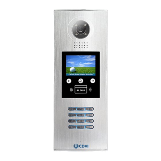
1/4 ACS 4T image sensor • Power consumption: Standby 33mA; Working status 157mA. • Screen: 3.5 inch TFT • Resolution: 320(R, G, B)X240 pixels • Video signal: CCIR/EIA optional • Wiring: 2 wires, non-polarity • Dimension: 350(H)×128(W)×46(D)mm DMR18S Technical Menu... - Page 4 0 : Enter the room number to call the monitor tools page. 1 : Enter the room number + ‘#’ to call the monitor * Note: In the diagram - 1) “0” mode is used as an example. 2) Shows setup of 2 digit calling. DMR18S Technical Menu...
-
Page 6: Configurations
[ - - - - - - - - ] (********) 3.Tone Volume: Select 3 to enter Tone Volume setting page. The setting range is 0 ~ 9. * Cancel # Save 3. Tone Volume [ - ] (0~9) * Cancel # Save DMR18S Technical Menu... - Page 7 S e t t i n g c o d e : 0 0 5 I nput 4 digits number, t hen press I n p u t n e w p a s s w o r d “#” to update. *Cancel # Save DMR18S Technical Menu...
- Page 8 8 digit number to set a new setup code, then press ‘#’ to save. [ 0 0 1 ] Updated Card Numbs.05410469 7. Setup Code ... * Cancel # Save [ - - - - - - - -] (********) * Cancel # Save DMR18S Technical Menu...
- Page 9 Please Input Password * Cancel # Save * Cancel # Save While working in debug Press NO.“6” to enter Enter the monitor code, state, press "1#" to enter Voltage Measure item. then press “#” to search. tools page. DMR18S Technical Menu...
-
Page 10: Work Mode
# Save Mode, for example enter the code 15 to call the monitor. 5. Doorplate Mode [11] [ * * * * * *1 1 ] 0: * 1: 123 2: ABC 3: - * Cancel # Save DMR18S Technical Menu... - Page 11 [ * * * 1 1 - 1 1 ] [ * * * * 1 - 1 1 ] 0: * 1: 123 0: * 2: ABC 1: 123 3: - 2: ABC * Cancel # Save 3: - * Cancel # Save -10- DMR18S Technical Menu...
-
Page 12: Software Update
'#' key the Code 87625761 SOFTWARE UPDATE 1. Format SD card 2. Copy the update software file (DMR18S.bin, provided by our company) to SD card by computer. TONE UPDATE 1. Format SD card 2. About the Ringtone file •... -
Page 13: Ui Update
5. Insert the SD card into the slot shown below, “Download...” will be displayed when the updated is in progress. After 3 seconds, a long sound “BEEP” will be heard to start the update. 6. When update is finished, it will return to Standby Mode interface. -12- DMR18S Technical Menu... -
Page 14: Namelist Update
BDU address 01~08 Address: Set the monitor address required • Edit NameList.txt file, for example, as the following picture shows: font.bin :100% image.idx :100% image.bin Enter101 or 1-01, it would call the monitor 01 in BDU 1. DMR18S Technical Menu -13-... -
Page 15: By Cdv-Config
Address: Monitor’s address (can be find in “about”); User Code: The number used to call the monitor; Name: The name of resident; Router: Sets the BDU address when in Router mode; Gateway: Sets the BDU address when in Gateway Mode. -14- DMR18S Technical Menu... - Page 16 • After editing, click “Download Table” to download Name List to the CDV-DDP; After a few seconds, a window will be displayed if it is updated successfully. • Click Download Room Table to download the namelist. DMR18S Technical Menu -15-...
- Page 17 Input 1-01 to call the monitor 01 connected to BDU 1 when the system is in Gateway mode, EX. enter 2-02 to call the monitor 02 connected to BDU 2, see the following picture: • Click Download Room Table to download the namelist. -16- DMR18S Technical Menu...
Need help?
Do you have a question about the DMR18S and is the answer not in the manual?
Questions and answers